Process for in situ bioremediation of subsurface contaminants

Inactive Publication Date: 2006-11-23
CDM SMITH
View PDF8 Cites 12 Cited by
  • Summary
  • Abstract
  • Description
  • Claims
  • Application Information

AI Technical Summary

Benefits of technology

[0021] This invention provides for the treatment of contaminated soil (e.g., contaminated soil in the vadose zone), groundwater, and perched water, including treatment of deep soil and perched water. The methods of the invention eliminate the need for costly pumping of groundwater and reduce the risk of biofouling of wells and equipment. This invention also does not require copious amounts of energy as are needed

Problems solved by technology

Subsurface contamination of soil, groundwater, and perched water has become a concern because such contamination has been associated with a number of detrimental health risks.
Perchlorate present in soil can leach into groundwater, and infiltrating storm water can increase the size of a contamination area.
Hence, perchlorate contamination of soil overlying groundwater is of particular concern.
Continuing contamination of groundwater by perchlorate sources in soil can result in the need to treat groundwater for extended time periods at a much greater cost.
One problem with this approach is that dispersion of injected liquid electron donors is limited and requires the use of closely spaced injection points.
One problem with this second approach is that pumping costs for groundwater can be high and the wells and equipment can be biofouled by the injected liquid electron donor.
Some in situ and ex situ anaerobic biological treatment methods have also been developed, however, these are limited to shallow soils and use liquid or solid electron donors that are difficult to deliver in situ.
Previous techniques for treating contamination of deep soil are extremely limited and have not been successful.
One example includes the percolation of liquid electron donors to deep soil, but these methods have

Method used


Image

  • Process for in situ bioremediation of subsurface contaminants
  • Process for in situ bioremediation of subsurface contaminants
  • Process for in situ bioremediation of subsurface contaminants

Examples


examples

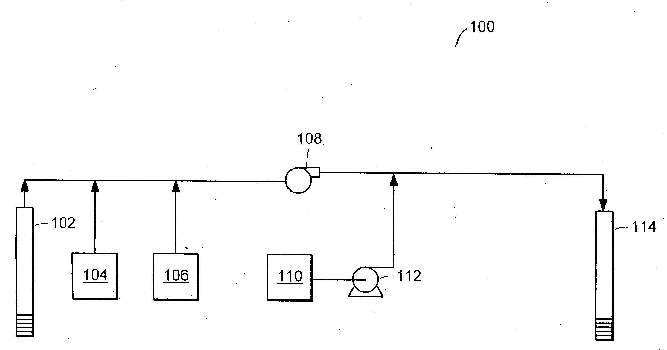
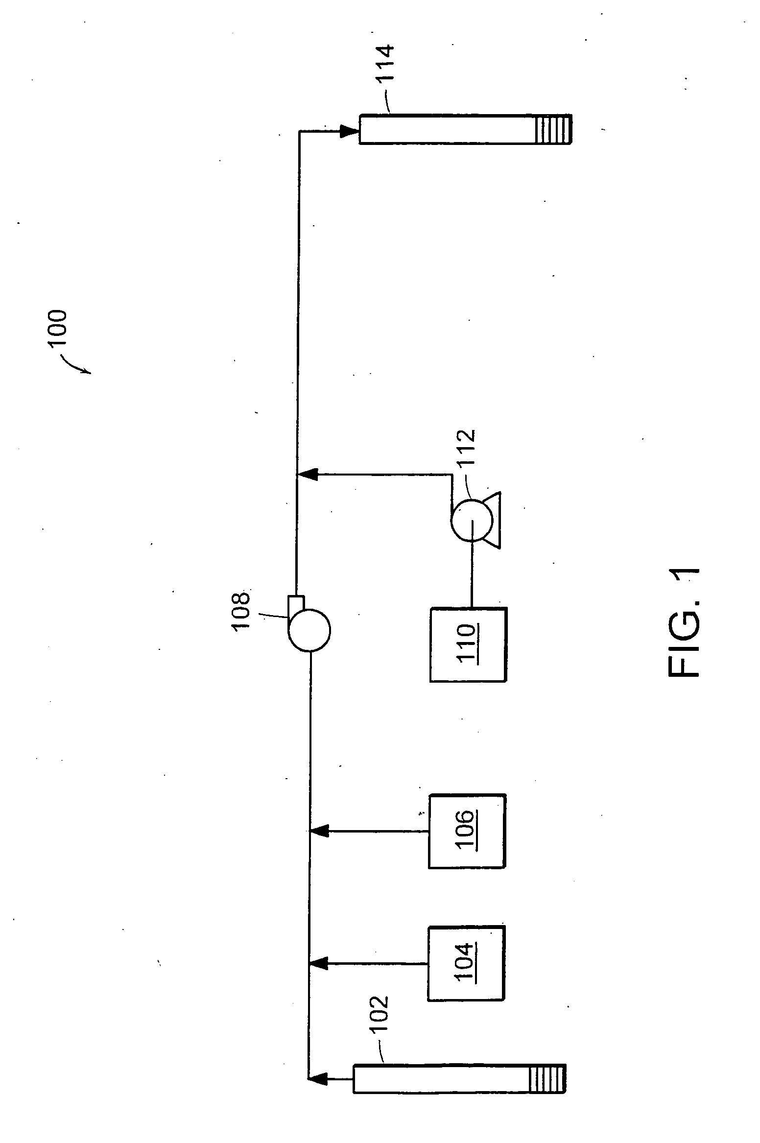
[0078] Samples were collected from a known contamination site in California. Simulated gas phase in situ biodegradation tests were conducted in 26-milliliter (mL) anaerobic pressure tubes sealed with thick butyl rubber stoppers and aluminum crimp seals. Soil was added to the tubes and they were then flushed with nitrogen to remove oxygen from the headspace. Amendments were then added to the tubes which were then incubated at room temperature in the dark.

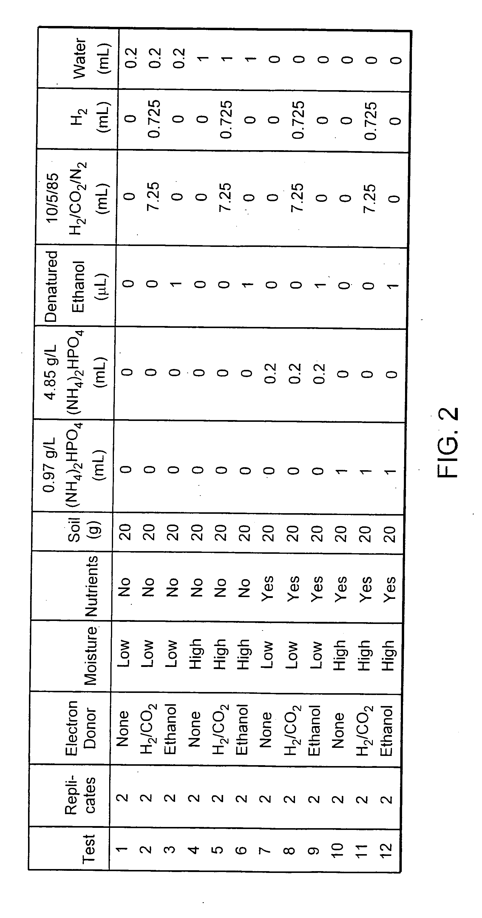
[0079] Twelve test conditions were set up and each was prepared in duplicate. FIG. 2 illustrates a table summarizing the twelve test conditions. The experimental design was that of a factorial experiment involving three factors each at two or three levels. The three factors and their associated levels were electron donor (none, hydrogen, or ethanol), moisture (low or high), nutrients (none or added). Carbon dioxide was added in addition to hydrogen as a source of carbon for growth.

[0080] Carbon dioxide and hydrogen were initially a...


PUM


Abstract

This invention includes methods of stimulating anaerobic degradation of subsurface contaminants. The methods include vaporizing a liquid electron donor to form a treating gas. The treating gas or hydrogen is directed to a subsurface site that includes one or more contaminants, thereby stimulating anaerobic degradation of the subsurface contaminants.

Description

RELATED APPLICATIONS [0001] This application is a continuation of International Application No. PCT / US2004 / 040013, which designated the United States and was filed on Nov. 30, 2004, published in English, which claims the benefit of U.S. Provisional Application No. 60 / 533,585, filed on Dec. 31, 2003, claims the benefit of U.S. Provisional Application No. 60 / 530,863, filed on Dec. 18, 2003, and claims the benefit of U.S. Provisional Application No. 60 / 528,803, filed on Dec. 11, 2003. The entire teachings of the above applications are incorporated herein by reference.BACKGROUND OF THE INVENTION [0002] Subsurface contamination of soil, groundwater, and perched water has become a concern because such contamination has been associated with a number of detrimental health risks. Subsurface contamination that includes perchlorate salts is a particular concern because the salts are soluble in water and capable of being transported long distances in underground aquifers. The U.S. Environmental...

Claims


Application Information

Patent Timeline
IPC IPC(8): B09C1/10B09C1/08B09C1/00
CPCB09C1/00B09C1/002B09C2101/00B09C1/10B09C1/08
Inventor EVANS, PATRICK J.
Owner CDM SMITH
Why Eureka
Try Eureka