
Narrow-band absorptive bandstop filter with multiple signal paths

Inactive Publication Date: 2006-12-07
THE UNITED STATES OF AMERICA AS REPRESENTED BY THE SECRETARY OF THE NAVY
View PDF12 Cites 62 Cited by
  • Summary
  • Abstract
  • Description
  • Claims
  • Application Information

AI Technical Summary

Benefits of technology

[0016] According to the invention, an absorptive bandstop filter includes at least two frequency-dependent networks, one of which constitutes a bandpass filter, that form at least two forward signal paths between an input port and an output port and whose transmission magnitude and phase characteristics are selected to provide a relative stopband bandwidth that is substantially independent of the maximum attenuation within the stopband and / or in which the maximum attenuation within the stopband is substantially independent of the unloaded quality factor of the resonators. The constituent network characteristics can also be selected to provide low reflection in the stopband as well as in the passband. The absorptive bandstop filter can be electrically tunable and can substantially maintain its attenuation characteristics over a broad frequency tuning range.
[0017] Significant advantages of a filter according to the invention include that the maximum attenuation is substantially independent of the unloaded quality factor of the resonators and can be essentially infinite, the reflection can be somewhat independent of the transmission and can be essentially zero in the stopband as well as in the passband even when the attenuation is essentially infinite, resonator frequency tuning alone can compensate for changes in filter component characteristics allowing for maintenance of filter characteristics over broad frequency tuning ranges, low stopband reflection can be maintained over moderate frequency tuning ranges, and both intrinsic and cascaded higher-order responses are realizable and the filter can exhibit better performance characteristics than a lossy elliptic function filter using similar components. First-order microstrip filters according to the invention can exhibit performance comparable to waveguide, dielectric resonator, and even superconductive filters. Yet the invention is not technology dependent, so that any resonator technology, even superconductive technology, can be applied in the realization of filters according to the invention—with corresponding improvements in performance.
[0018] Active-circuit filter embodiments can be significantly smaller, less expensive, more reliable, less prone to amplifier instability, exhibit lower insertion loss, and / or possess lower-distortion filter realizations than prior art active approaches.
[0019] The ability to realize low stopband reflection together without sacrificing stopband attenuation can be advantageous when the filter is cascaded with an amplifier, as amplifier design constraints are eased if one or both of the amplifier port impedances is known to be constant over all frequencies of interest. This low stopband reflection property can be particularly helpful in maintaining amplifier stability in frequency agile filter applications.
[0020] Passive reciprocal embodiments of the invention can advantageously utilize inexpensive, inherently stable, inherently low-distortion, monolithic-manufacturing-process compatible, conventional materials and components technologies.
[0023] The present invention improves resonator effective Qu and provides more compact, more affordable, and more reliable circuit topologies and realizations for which maximum attenuation is independent of resonator Qu. The present filter significantly extends the state of the art in miniature, inexpensive, high performance, and frequency-agile notch filters.

Problems solved by technology

Unfortunately, in these types of bandstop filters, the relative bandwidth b=f12-fo2f1⁢fo
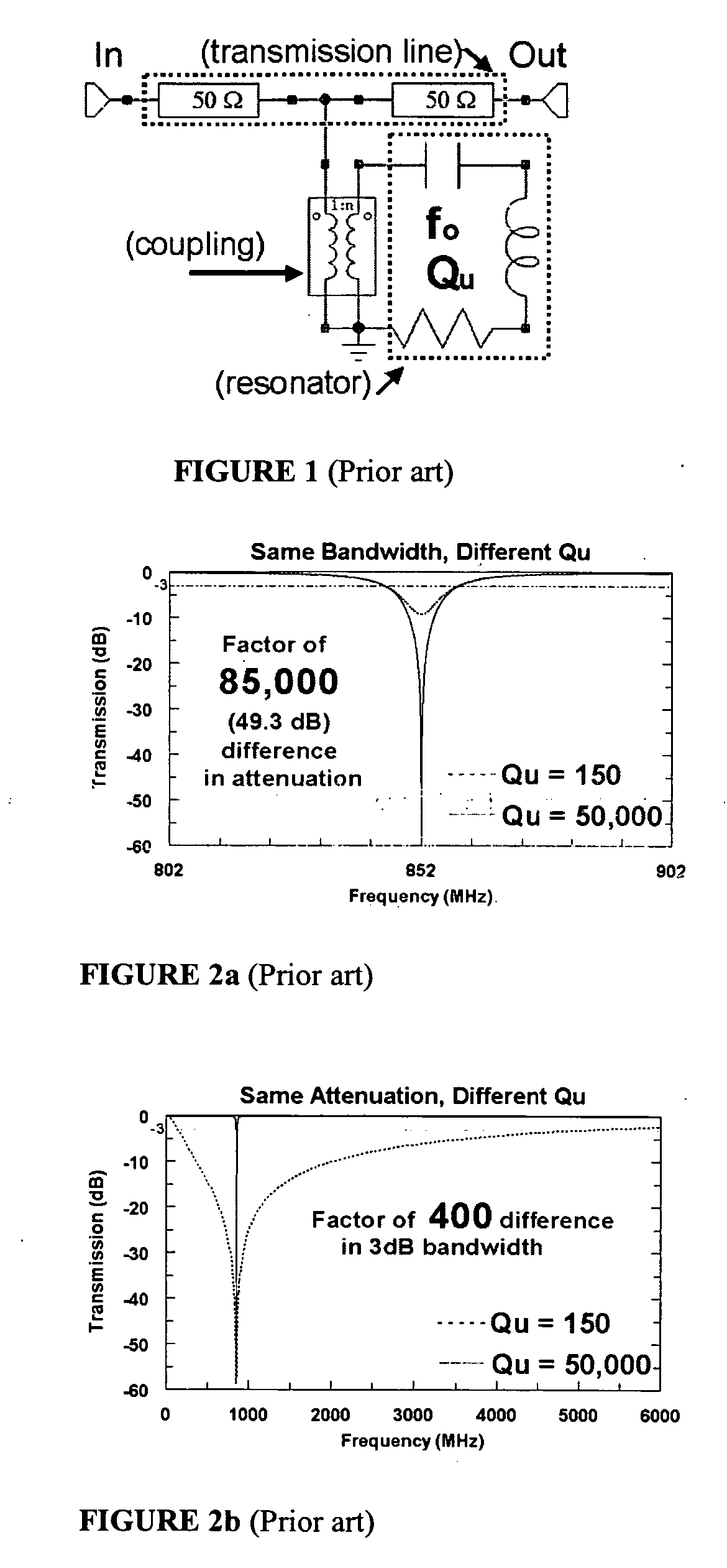
Also, for a fixed level of coupling between the resonance and the transmission line, the maximum attenuation is dependent on the resonator Qu, so that a resonance with a lower Qu results in a wider relative bandwidth, smaller maximum attenuation, and lower filter selectivity.
The only means of realizing better performance from optimally designed conventional notch filters is to employ resonators with commensurately higher Qu, which means either using relatively large waveguide cavity resonators, significantly smaller, but heavy and moderately expensive, single-mode or dual-mode dielectric resonators, or very expensive superconducting resonators that require cryogenic packaging and a cryocooler.
Using higher Qu resonators unavoidably requires accepting some combination of a larger volume, a heavier weight, and a greater cost, as well as inherent incompatibility with conventional printed-circuit and integrated-circuit manufacturing processes.
A disadvantage, however, is that the values of the constituent lumped inductors and capacitors must be exceptionally precise and that the ratios of the inductor values and the capacitor values in the circuits are impractically large.
Consequently, it has not found wide use, especially at microwave frequencies where realizing lumped inductors is problematic.
The approach, however, suffers from instability (a tendency to oscillate) inherent to positive feedback schemes, and while the approach significantly improves the stopband attenuation, it fails to improve, and can actually degrade, the band-edge noise figure.
The noise, gain nonlinearities, and signal distortion inherent in any such amplifier in an all-pass signal path makes the invention generally unsuitable for many important applications, including receiver pre-select filtering and transmitter clean-up filtering.
Unfortunately, circulators are generally connectorized components, and although they can be made compatible with hybrid circuit manufacturing, they are generally much larger than semiconductor amplifiers and are incompatible with conventional monolithic printed-substrate and integrated circuit processing.
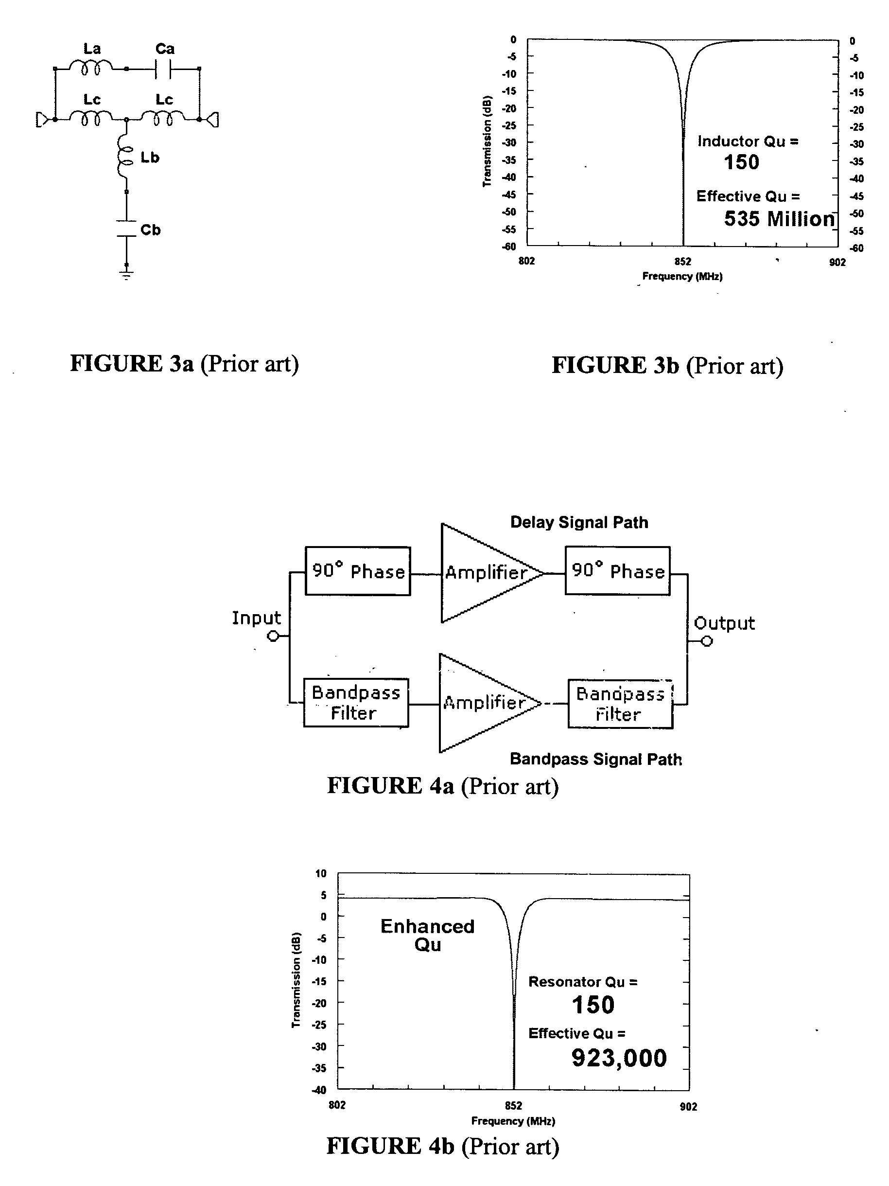
Although this provides a low-distortion, amplifier-free “delay” signal path, it requires twice as many amplifiers and resonators, and three times the transmission line length and its associated insertion loss in the delay path.
Conventional tunable bandstop filters suffer appreciable performance variation and degradation over their frequency tuning range due to frequency dependent loss in the tuning elements and resonators, as well as frequency dependent coupling magnitude and frequency dependent phase shift in the coupling elements.

Method used


Image

  • Narrow-band absorptive bandstop filter with multiple signal paths
  • Narrow-band absorptive bandstop filter with multiple signal paths
  • Narrow-band absorptive bandstop filter with multiple signal paths

Examples


embodiment 1200

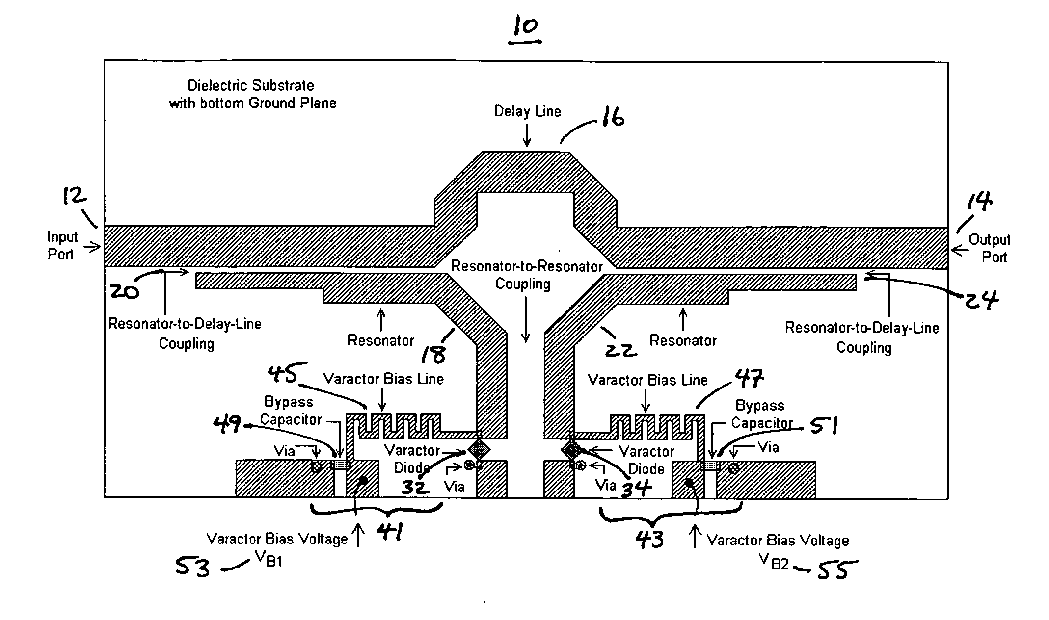
[0167] As an example, the performance of a fourth-order filter (with eight resonators), comprised of a cascade, according to invention embodiment 1200 of FIG. 38a, of two of the passive biquad subcircuits 700 of FIG. 21a, was analyzed with a microwave circuit simulator. The cascaded network 1200 was designed to achieve a stopband width of 10 MHz at a center frequency of 2 GHz (γ=0.5% relative stopband bandwidth) and a minimum stopband attenuation of 45 dB using resonators with Qu=200 (the approximate Qu of 87 Ω microstrip resonators on a 1.5 mm thick Rogers RO4003C substrate). The impedance inverter 706 was implemented using a quarter wavelength lossy microstrip transmission line. The simulated performance of the two individual passive biquad subcircuits 700, together with that of the fourth-order cascade 1200, is shown in FIG. 25. For comparison, a “conventional” quasi-elliptic eighth-order bandstop filter was also simulated. Its eight resonators also had Qu=200 and were coupled to...

embodiment 10

[0178] Further, it will also be appreciated that the teachings of the previously referenced U.S. Pat. No. 5,781,084 with respect to the design and synthesis of one-port reflection-mode filters including a ladder network of resonators having progressively reducing Q values can be applied to the design and synthesis of the one-port admittances Yp 26 and Ym 28 of filter embodiment 10 as shown in FIG. 5c.


PUM


Abstract

An absorptive bandstop filter includes at least two frequency-dependent networks, one of which constitutes a bandpass filter, that form at least two forward signal paths between an input port and an output port and whose transmission magnitude and phase characteristics are selected to provide a relative stopband bandwidth that is substantially independent of the maximum attenuation within the stopband and / or in which the maximum attenuation within the stopband is substantially independent of the unloaded quality factor of the resonators. The constituent network characteristics can also be selected to provide low reflection in the stopband as well as in the passband. The absorptive bandstop filter can be electrically tunable and can substantially maintain its attenuation characteristics over a broad frequency tuning range.

Description

FIELD OF THE INVENTION [0001] This invention relates to a bandstop filter. More particularly, the invention relates to a tunable narrow-band absorptive bandstop, or notch, filter. BACKGROUND OF THE INVENTION [0002] Currently, there is significant interest in narrow-band bandstop, or notch, filters for use in advanced communication systems. A notch filter is used in the signal path of a receiver or transmitter to suppress undesired signals in a narrow band of frequencies, signals that would otherwise compromise system performance. For example, notch filters can be used to remove interference from receiver front-ends due to collocated transmitters, adjacent receive bands, and jammers, and can be used in transmitters to eliminate harmonic and spurious signals due to power amplifier nonlinearities. [0003] Any means of attenuating electromagnetic power over a limited frequency band or bands is typically called a bandstop, band-reject, or notch filter. Conventional notch filter performanc...

Claims


Application Information

Patent Timeline
IPC IPC(8): H01P1/203
CPCH01P1/2039
Inventor JACHOWSKI, DOUGLAS R.
Owner THE UNITED STATES OF AMERICA AS REPRESENTED BY THE SECRETARY OF THE NAVY
Learn More