X-ray high voltage device

a high-voltage device and x-ray technology, applied in the direction of x-ray equipment, electrical equipment, etc., can solve the problems of reducing the life of the x-ray, affecting the effect of treatment, so as to reduce the size of the x-ray, reduce the ineffective exposure, and simplify the high-voltage side.

Inactive Publication Date: 2006-12-07
HITACHI MEDICAL CORP
View PDF14 Cites 40 Cited by
  • Summary
  • Abstract
  • Description
  • Claims
  • Application Information

AI Technical Summary

Benefits of technology

[0012] Since the X-ray high voltage device according to the present invention regenerates the energy of electric charges stored in the high voltage capacitor to the DC voltage source such as the smoothing capacitor, such as the current limiting use impedance and the regeneration use high voltage transformer which were required in conventional art are unnecessitated, the structure of the high voltage side is simplified and the size thereof is reduced and further, since the wave tail of the tube voltage can be dropped rapidly, the ineffective exposure can be reduced. Moreover, the energy regenerated into the smoothing capacitor can be effectively utilized for generation of the subsequent tube voltage pulse.
[0013] Further, the low voltage side inverter is constituted so as to perform a switching control in which shorting and opening of the primary side of the high voltage transformer is repeated periodically for regenerating the energy of the electric charges stored in the high voltage capacitor. Thereby, the low voltage side inverter is operated as a chopper circuit which at least turns on a switch in the low voltage side inverter and turns off the same in earlier timing than the frequency of the AC voltage and thereby chops the current flowing through the parasitic leakage inductance. Thereby, the current flowing through the parasitic leakage inductance is rapidly sent out to the smoothing capacitor 12 and charges the same. Namely, by making use of the parasitic leakage inductance of the primary winding of the high voltage transformer, the energy of the electric charges stored in the high voltage capacitor can be regenerated to the primary side of the high voltage transformer.

Problems solved by technology

Therefore, in an X-ray high voltage device which is required to generate a high speed pulse shaped tube voltage so as to perform cinematic photography which photographs bloodstream in blood vessel on cinematic films as an animating picture and a pulsating fluoroscopy which is for obtaining high quality and real time images of a region of interest when manipulating a catheter in a blood vessel such as for a medical use X-ray device, a waveform of the tube voltage when dropping (herein below will be called as wave tail) causes a problem.
Namely, such wave tail shows almost no effect on X-ray images formed on X-ray films and X-ray TV, moreover, the wave tail causes the X-ray tube to irradiate many amount of low energy X-ray which likely causes a harmful exposure to a subject.
Such ineffective exposure caused by the wave tail can in particular impede medical treatment under high quality fluoroscopy represented by interventional radiology.
Further, during the wave tail period of the tube voltage, since the power stored in the high voltage capacitor is consumed by the X-ray tube, the internal temperature of the X-ray tube is increased accordingly, thereby, the life time of the X-ray is shortened as well as limitations such as lowering permissible X-ray conditions after pulse shape X-ray outputting are possibly caused.
Namely, during performing the pulse fluoroscopy, electric power to the extent of 1.5 kW is always lost in the current limiting impedance to generate heat.
For this reason the current limiting impedance has to be cooled, which necessitates a separate cooling device and also complexes the structure of the high voltage part.

Method used


Image

  • X-ray high voltage device
  • X-ray high voltage device
  • X-ray high voltage device

Examples


embodiment 2

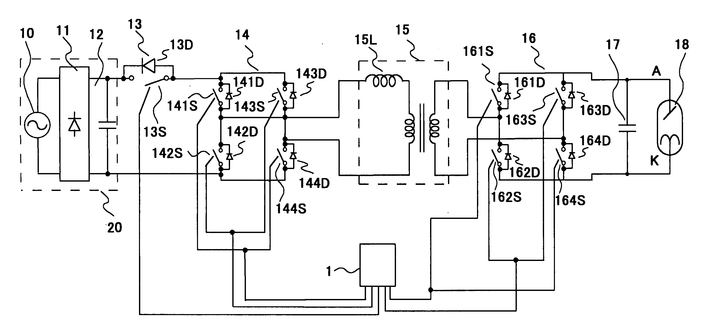
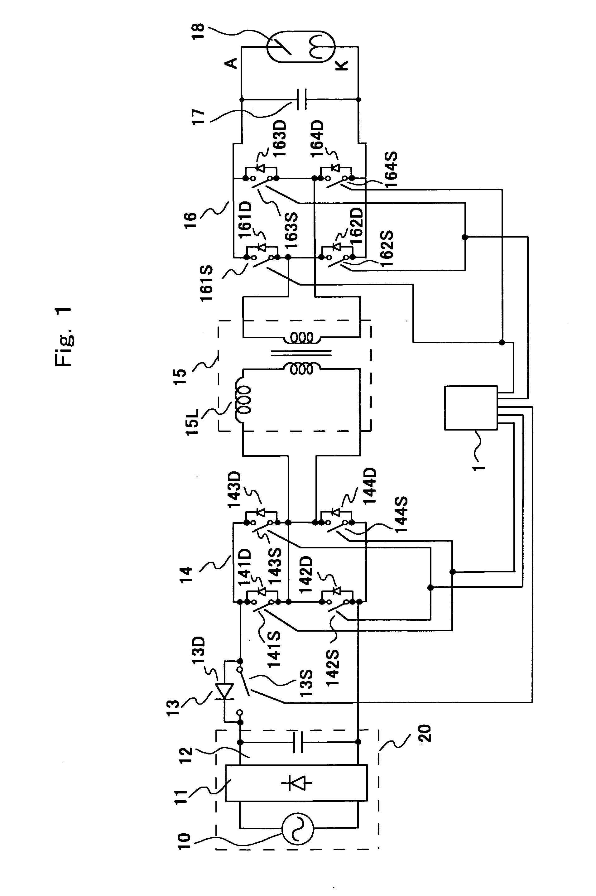
[0053]FIG. 3 is a circuit diagram showing an X-ray high voltage device according to another embodiment of the present invention.

[0054] The X-ray high voltage device according to the present embodiment uses a neutral point grounded type X-ray tube 18a, thereby, the withstanding voltage of the high voltage cables is halved to 75 kV, the secondary winding of a high voltage transformer 15 is divided into two parts one for the anode side of the X-ray tube 18a and the other is for the cathode side thereof and a high voltage inverter 16 is constituted by an anode side high voltage inverter 16a including switching means 161S˜164S connected to the secondary winding of the anode side and diodes 161D˜164D and a cathode side high voltage inverter 16b including switching means 165S˜168S connected to the secondary winding of the cathode side and diodes 165D˜168D.

[0055] In this type of the X-ray high voltage device, like the embodiment 1 as has been explained above, with respect to a smoothing c...

embodiment 3

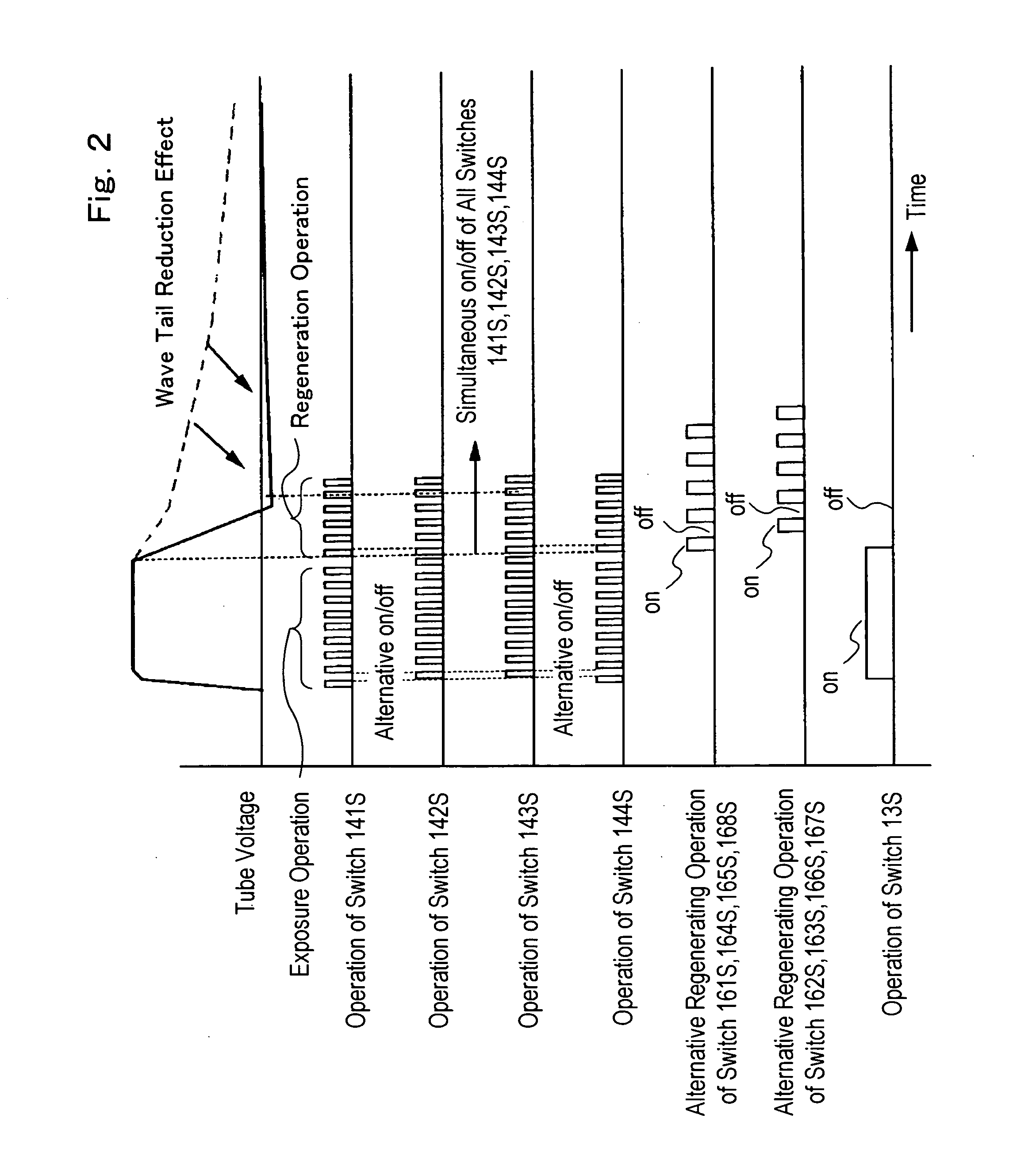
[0061]FIGS. 5 and 6 are operation waveform diagrams showing an operation of an X-ray high voltage device according to a further embodiment of the present invention.

[0062] Although in the X-ray high voltage devices shown in connection with FIGS. 1 and 3 embodiments, when dropping the tube voltage of the X-ray tubes 18 and 18a at t2 in FIG. 7, the switching means 141S˜144S in the low voltage side inverter 14 are simultaneously turned on and off, however, in the present embodiment, when dropping the tube voltage, the switching means of one group in the bridge connection are always turned off and only the remaining other group are simultaneously on and off controlled. Namely, in FIG. 5 embodiment, the switching means 142S and 144S are simultaneously on and off controlled while keeping the switching means 141S and 143S turned off, and in FIG. 6 embodiment, the switching means 141S and 143S are simultaneously on and off controlled while keeping the switching means 142S and 144S turned of...


PUM


Abstract

A semiconductor switch 12 connected in series with a smoothing capacitor 12 is constituted by connecting in parallel a diode 13D which permits to flow current regenerated from energy of electric charges stored in a high voltage capacitor 17 to a primary side of a high voltage transformer 15 for the smoothing capacitor 12 and switching means 13S which interrupts an output from the smoothing capacitor 12, and after turning off the switching means 13S, through alternative on and off control of switching means 161164S the energy of electric charges stored in the high voltage capacitor 17 is regenerated to the smoothing capacitor 12 by making use of parasitic leakage inductance 15L. As a result, an X-ray high voltage device is provided which permits to drop a wave tail of a tube voltage in a high speed without complexing the structure of the high voltage part thereof.

Description

FIELD OF THE INVENTION [0001] The present invention relates to a medical or industrial use X-ray high voltage device which applies a high voltage to an X-ray tube therein. CONVENTIONAL ART [0002] An X-ray high voltage device is generally constituted in such a manner that after rectifying an AC voltage with a rectifier circuit, the rectified voltage is smoothed by a smoothing capacitor and then inverted into a high frequency AC voltage with a low voltage side inverter, the high frequency AC voltage is boosted up with a high voltage transformer of which primary winding is connected to the low voltage side inverter, the boosted up AC high voltage is rectified and inverted into a DC high voltage with a high voltage rectifier to which a secondary winding of the high voltage transformer is connected, the inverted DC high voltage is smoothed by such as a capacitor added to the high voltage side and a high voltage capacitor constituted by a stray capacitance included in high voltage cables ...

Claims


Application Information

Patent Timeline
Patent Type & Authority Applications(United States)
IPC IPC(8): H05G1/12H05G1/20
CPCH05G1/12
Inventor SAKAMOTO, KAZUHIKOTAKANO, HIROSHI
Owner HITACHI MEDICAL CORP
Why Eureka
Try Eureka