Sealed rechargeable battery and manufacturing method of the same

a rechargeable battery and manufacturing method technology, applied in the direction of batteries, sustainable manufacturing/processing, cell components, etc., can solve the problems of increasing the contact resistance of internal parts, reducing the crimp strength, and losing the resiliency of polypropylen

Inactive Publication Date: 2006-12-07
PANASONIC CORP
View PDF7 Cites 46 Cited by
  • Summary
  • Abstract
  • Description
  • Claims
  • Application Information

AI Technical Summary

Benefits of technology

[0027]FIG. 1 is a schematic longitudinal cross-sectional view of a cylindrical lithium ion battery according to one embodiment of the invention. The battery includes a cylindrical electrode unit 4 that consists of a positive electrode 1 and a negative electrode 2 coiled around with a 25 μm thick separator 3 interposed therebetween. The positive electrode 1 is made of an aluminum foil collector and a positive electrode mixture deposited thereon, and the negative electrode 2 is made of a copper foil collector and a negative electrode mixture deposited thereon. A collector lead 5 of the positive electrode is connected to the aluminum foil collector by laser welding, and a collector lead 6 of the negative electrode is connected to the copper foil collector by resistance welding. The electrode unit 4 is encased in a metallic case 7 with a bottom. The collector lead 6 of the negative electrode is electrically connected to the bottom of the case 7 by resistance welding. The collector lead 5 of the positive electrode is electrically connected to the metallic filter 9 of the closure assembly 8 through the open end of the case 7 by laser welding. Non-aqueous liquid electrolyte is poured into the case 7 from its open end. A groove is formed at the open end of the case 7 to provide a seat, on which a resin outer gasket 15 and the closure assembly 8 are set, with the collector lead 5 being bent, and the entire circumference of the open end edge of the case 7 is crimped to provide a seal.
[0028] Examples of the positive electrode active material include a complex oxide such as lithium cobalt oxide, lithium nickel oxide, and lithium manganese oxide, or modified complex oxides. The modified complex oxide may contain aluminum or magnesium element, and/or cobalt, nickel, or manganese element.
[0029] The positive electrode active material is mixed with a conductor ...

Problems solved by technology

However, synthetic resin such as polypropylene loses its resiliency over time during which it may be dropped, vibrated, or stored at high temperature, because of which the crimp strength decreases and contact resistance of internal parts increases.
I...

Method used


Image

  • Sealed rechargeable battery and manufacturing method of the same
  • Sealed rechargeable battery and manufacturing method of the same
  • Sealed rechargeable battery and manufacturing method of the same

Examples


example 1

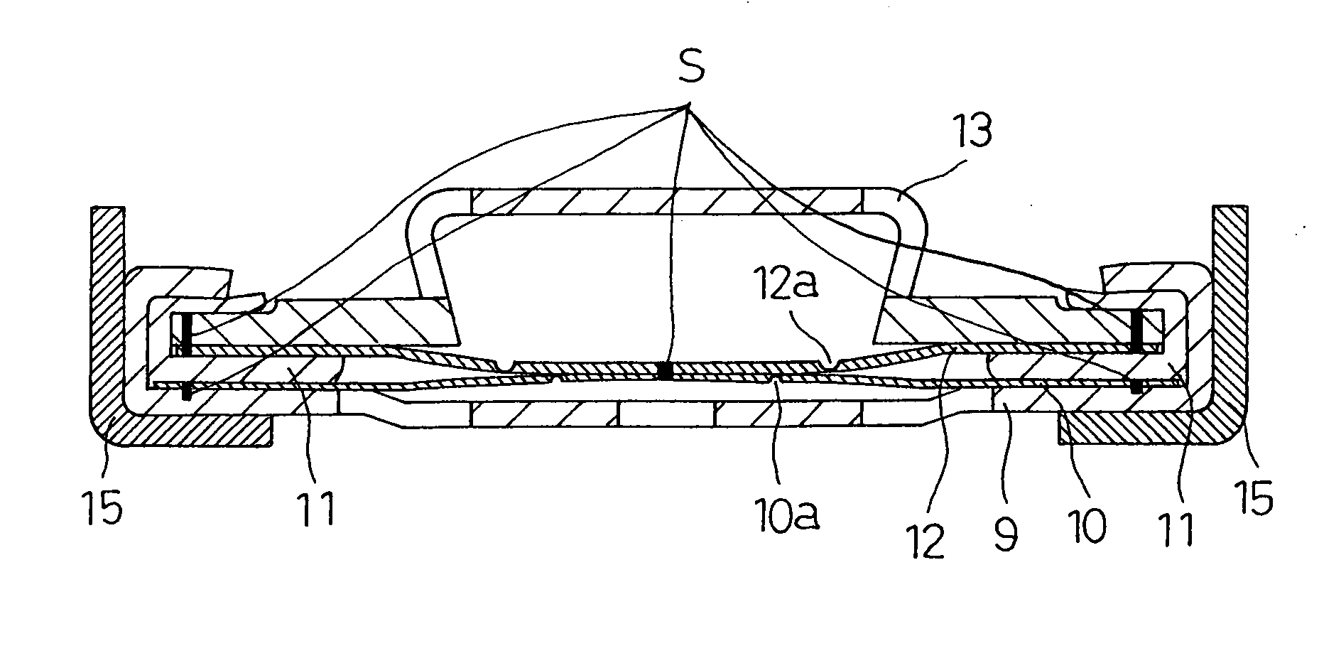
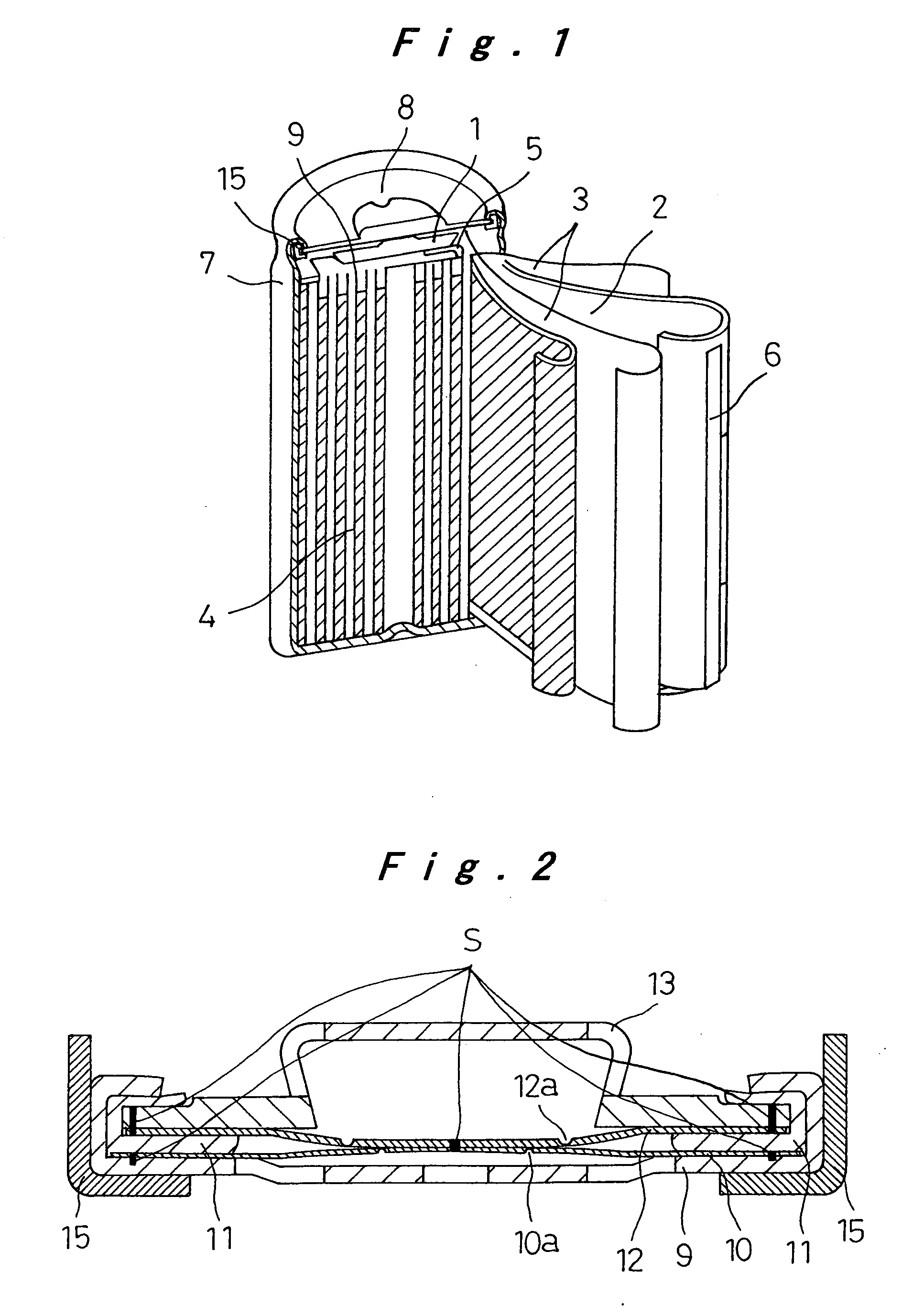
[0037]FIG. 2 shows the closure assembly in the sealed rechargeable battery of the invention. The closure assembly 8 of FIG. 2 is fabricated as follows: Dish-like metallic filters 9 with a plurality of apertures are produced from aluminum sheet by press-forming. Aluminum discs of 0.15 mm thickness are punched out, and circular thin portions 10a are created in the center of the discs by imprinting, to produce metallic foils10. Inner gaskets 11 with predetermined dimensions are produced from polybutylene terephthalate (PBT) by injection molding. Aluminum discs of 0.15 mm thickness are punched out, and C-shaped thin portions 12a are created in the center of the discs by imprinting, to produce metallic safety vents 12. Metallic caps 13 are produced by press-forming and nickel-plating iron sheet to a thickness of about 3 μm. These parts that will make up the closure assembly 8 are then assembled as follows: The metallic foil 10 is placed on the seat of the metallic filter 9, and laser-wel...

example 2

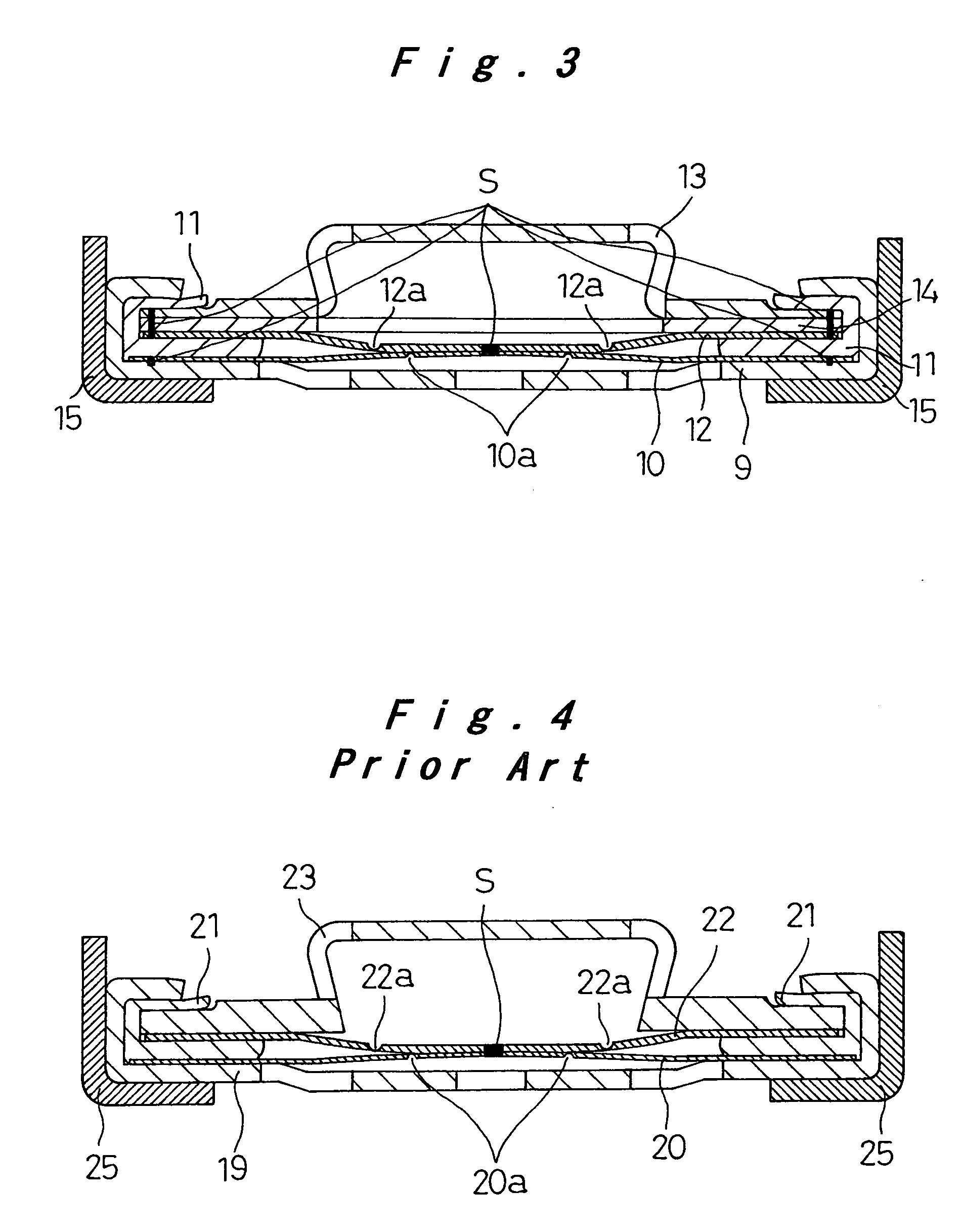
[0042]FIG. 3 shows another closure assembly 8 of the sealed rechargeable battery of the invention. The battery itself is produced similarly to Example 1. The closure assembly 8 includes a disc-like metallic spacer 14 as shown in FIG. 3, made by press-forming a nickel-plating stainless steel sheet to a thickness of 3 μm. The metallic spacer 14 is joined to the metallic cap 13 at eight circumferentially equally spaced weld joints S in the periphery by resistance welding. These joined parts are laser-welded to the metallic safety vent 12 at eight circumferentially equally spaced locations S in the periphery. These joined parts are then inserted onto the resin inner gasket 11 such that the metallic safety vent 12 is in contact with the upper surface of the gasket. Apart from the above difference in the closure assembly, Example 2 of the battery is the same as Example 1.


PUM

PropertyMeasurementUnit
Electrical resistanceaaaaaaaaaa
Temperatureaaaaaaaaaa

Abstract

A sealed rechargeable battery containing an electrode unit and a liquid electrolyte in a metallic case with a bottom that is sealed with a closure assembly. The electrode unit includes a positive electrode and a negative electrode, each made up of a collector and electrode material paste coated thereon, wound around with a separator interposed therebetween. The closure assembly includes a metallic filter that forms an internal terminal and accommodates a safety mechanism provided in case of abnormal pressure rise caused by overcharging etc, a resin inner gasket, and a metallic cap that forms an external terminal superposed upon one another. A resin inner gasket is attached to the metallic filter and the end edge of the metallic filter is crimped to provide a seal. The metallic filter and all the metallic parts encased in the metallic filter are joined together by welding. This closure assembly design enables high power output and high-current discharge of the battery with low resistance.

Description

[0001] The present disclosure relates to subject matter contained in priority Japanese Patent Applications No. 2005-142643, filed on May 16, 2005, and No. 2006-120967, filed on Apr. 25, 2006, the contents of which is herein expressly incorporated by reference in its entirety. BACKGROUND OF THE INVENTION [0002] 1. Field of the Invention [0003] The present invention relates to a sealed rechargeable battery suitable for use as a driving power source, and more particularly to its closure assembly design with low resistance suitable for high-current discharge, and the manufacturing method of the battery. [0004] 2. Description of the Related Art [0005] Sealed rechargeable batteries, and particularly lithium ion rechargeable batteries, are small, lightweight, and high in energy density, and therefore used for various purposes ranging from consumer electronic equipment such as mobile phones to driving power sources of electric vehicles or electric tools. It is considered particularly suitab...

Claims


Application Information

Patent Timeline
IPC IPC(8): H01M2/08H01M2/12H01M10/04H01M50/167H01M50/184H01M50/186H01M50/193
CPCH01M2/0413H01M2/08H01M2/1241Y10T29/4911H01M10/0587H01M2200/20Y10T29/49114H01M2/345Y02E60/10H01M50/171H01M50/3425H01M50/578Y02P70/50H01M50/184H01M50/186H01M50/193H01M50/167
Inventor KOZUKI, KIYOMIHASHIMOTO, TATSUYAINOUE, KOKIHIRAKAWA, YASUSHI
Owner PANASONIC CORP
Why Eureka
Try Eureka