

Integrated circuit having a low power, gain-enhanced, low noise amplifying circuit
- Summary
- Abstract
- Description
- Claims
- Application Information
AI Technical Summary
Benefits of technology
Problems solved by technology
Method used
Image

Examples
first embodiment
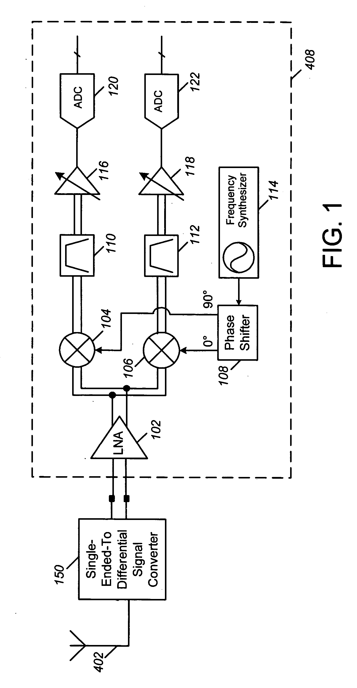
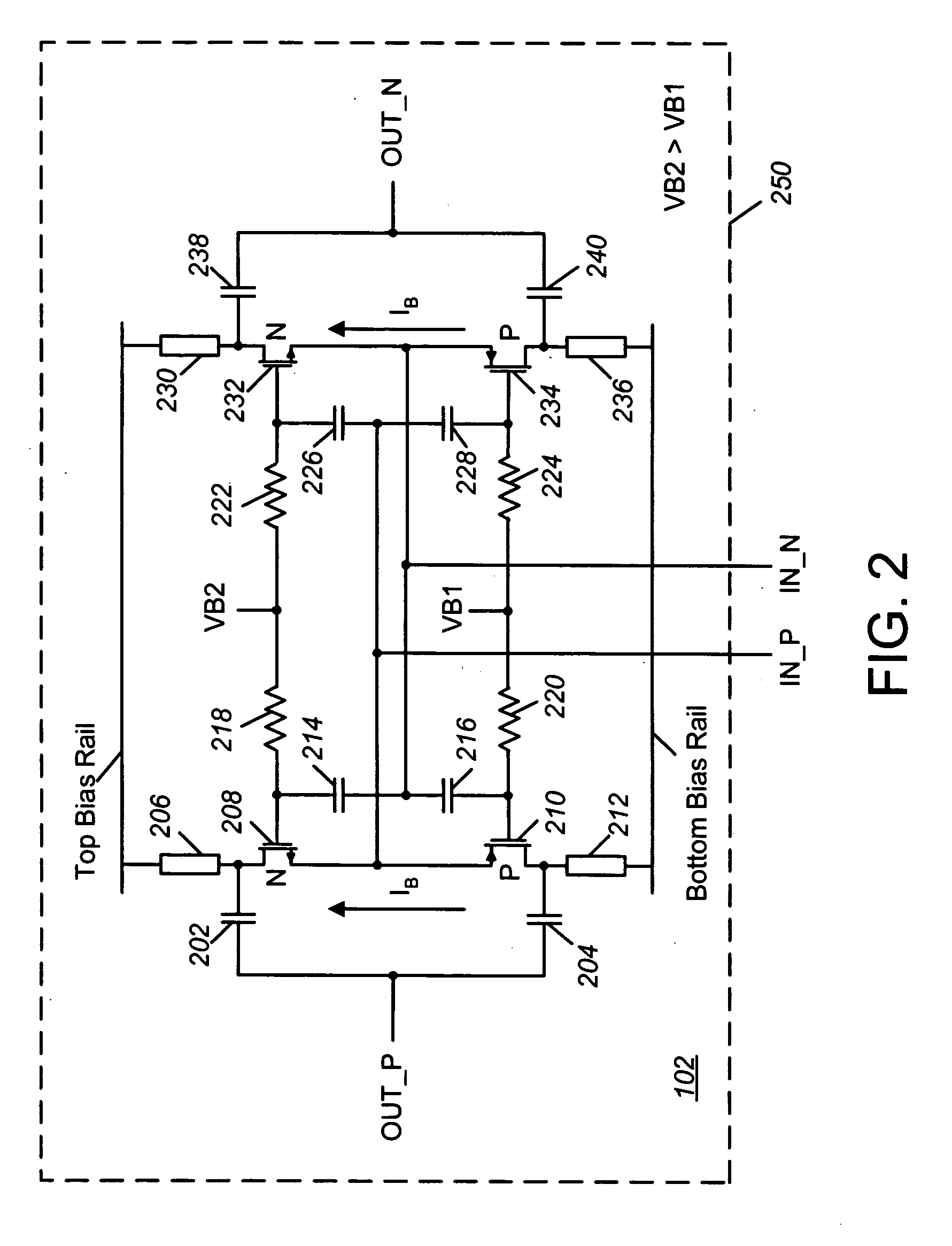
[0019] Referring now to FIG. 2, a schematic diagram of a low power, gain-enhanced, low noise amplifying (LNA) circuit 102 of the present application is shown. In FIG. 2, amplifying circuit 102 is a full differential amplifier (i.e. both the input signal and the output signal are fully differential) which may be used as LNA 102 of FIG. 1. Amplifying circuit 102 is preferably embodied in an integrated circuit (IC) 250.
[0020] A differential input signal is presented at the differential input of LNA 102 which is represented by IN_N and IN_P nodes. The differential input (i.e. the IN_N and IN_P nodes) is provided at and exposed externally on IC 250 in the form of conductive pads or leads. As shown in FIG. 2, the IN_N node is coupled to first ends of capacitors 214 and 216, a source of a negative-channel (n-channel) transistor 232, and a source of a positive-channel (p-channel) transistor 234. Preferably, n-channel transistor 232 is an N-channel Metal Oxide Semiconductor Field Effect Tran...
second embodiment
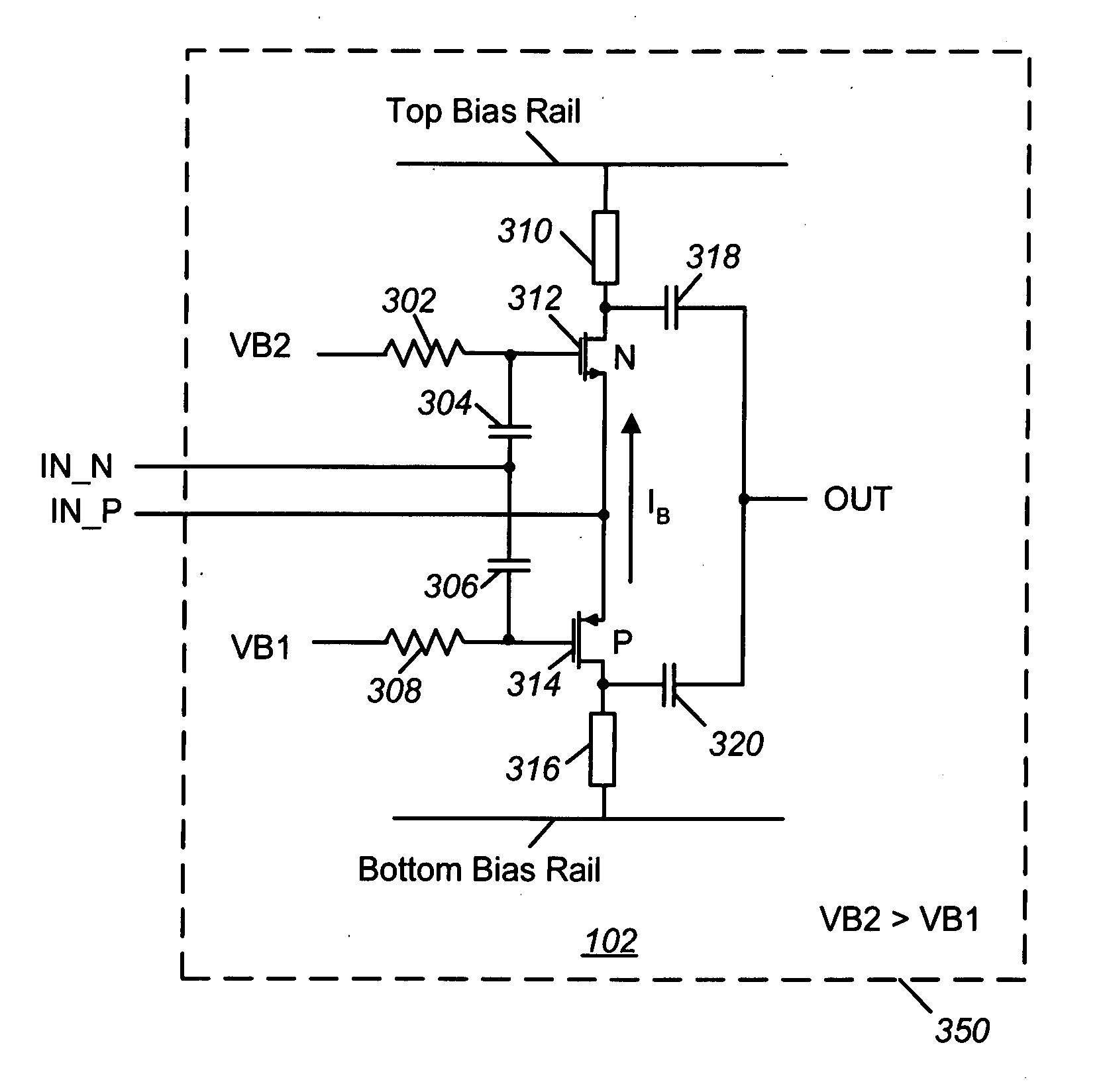
[0026]FIG. 3 is amplifying circuit 102 of the present application which is embodied within an IC 350. Amplifying circuit 102 of FIG. 3 provides an input which is adapted to receive a differential signal, but an output that is single-ended. Otherwise, the amplifying circuit of FIG. 3 is similarly structured and functions as a half portion of the amplifying circuit of FIG. 2.
[0027] Amplifying circuit 102 of FIG. 3 includes an n-channel transistor 312, a p-channel transistor 314, capacitors 304, 306, 318, and 320, impedance circuits 310 and 316, and resistors 302 and 308 (optional). A differential input is represented by and at IN_N and IN_P nodes, whereas a single-ended output is represented by and at an OUT node. The IN_N node is provided at first ends of capacitors 304 and 306, which have second ends coupled to the gates of transistors 312 and 314, respectively. The IN_P node is provided at sources of transistors 312 and 314. A drain of n-channel transistor 312 is coupled to a first...
PUM
 Abstract
Description
Claims
Application Information