
Lithium secondary battery

a secondary battery and lithium battery technology, applied in the field of lithium secondary batteries, can solve the problems of difficult stably supply lithium secondary batteries, theoretical capacities cannot be considered very high, etc., and achieve the effect of reducing safety and increasing the energy density of the electrode group

Active Publication Date: 2006-12-21
PANASONIC CORP
View PDF11 Cites 18 Cited by
  • Summary
  • Abstract
  • Description
  • Claims
  • Application Information

AI Technical Summary

Benefits of technology

[0006] The present invention was made in view of the foregoing problems, and it is an object of the invention to improve the safety during an internal short circuit and the storage characteristics of a lithium secondary battery having a high energy density.
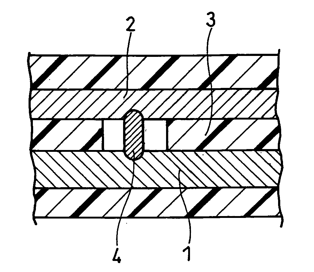
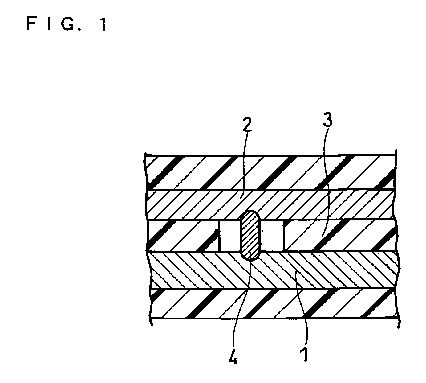
[0028] In the case where a short circuit has occurred between the positive electrode and the negative electrode, conventional separator layers will be melted by heat generated, since they only include a porous resin membrane. Consequently, the area of the short circuit portion increases to the total of the short circuit area A and the reduced area of the separator layer, further increasing the amount of heat generated. The amount of heat generated at the time of occurrence of a short circuit significantly increases when the energy density of the electrode group exceeds 700 Wh / L. Particularly, when an internal short circuit has occurred during storage in a high temperature environment and the short circuit portion expands, then the heat generation is greatly accelerated. On the other hand, the separator layer according to the present invention includes the porous heat-resistant layer, and the reduced area B of the porous heat-resistant layer that has resulted from the heat generated during a short circuit is limited to a small amount. Accordingly, it is possible to reduce the duration of a short circuit, thereby suppressing the increase of the amount of heat generated, or the acceleration of the heat generation. Thus, according to the present invention, it is possible to provide a lithium secondary battery that offers a high level of safety in case of an internal short circuit and excellent storage characteristics, while having a high energy density.

Problems solved by technology

These theoretical capacities cannot be considered very high.
Thus, it is difficult to stably supply lithium secondary batteries including an electrode group with an energy density of not less than 700 Wh / L.

Method used


Image

  • Lithium secondary battery
  • Lithium secondary battery

Examples


example 1

[0087] A lithium secondary battery was designed such that its working voltage range was from 2.5 V to 4.2 V (end-of-discharge voltage: 2.5 V, end-of-charge voltage: 4.2 V).

(i) Production of Positive Electrode

[0088] A positive electrode material mixture paste was prepared by stirring, with a double arm kneader, 5 kg of a lithium nickelate powder (median diameter: 20 μm) serving as a positive electrode active material, 1 kg of an N-methyl-2-pyrrolidone (NMP) solution (#1320 (trade name) manufactured by KUREHA CORPORATION) containing 12 wt % of polyvinylidene fluoride (PVDF) serving as a binder, 90 g of acetylene black serving as a conductive agent and a suitable amount of NMP serving as a dispersion medium. The positive electrode material mixture paste was applied onto both sides of a band-shaped positive electrode current collector comprising an aluminum foil with a thickness of 15 μm. The applied positive electrode material mixture paste was dried, and rolled with rollers to form...

example 2

[0093] A lithium secondary battery was fabricated in the same manner as Example 1, except that a SiO powder (median diameter: 8 μm) was used in place of the powder composed simply of silicon, and that the dimensions of the positive electrode and the negative electrode were changed as necessary based on the above-described design standard (i.e. with the working voltage range of the lithium secondary battery being set to 2.5 V to 4.2 V, and the volume of the electrode group being set to be the same as that in Example 1). The theoretical capacity of the battery was 3203 mAh, and the energy density of the electrode group was 824 Wh / L.

example 3

[0094] A negative electrode material mixture paste was prepared by stirring, with a double arm kneader, 4 kg of a powder composed simply of tin (Sn) (median diameter: 10 μm) serving as a negative electrode active material, 250 g of an aqueous dispersion (BM-400B (trade name) manufactured by ZEON Corporation) containing 40 wt % of modified styrene butadiene rubber particles serving as a binder, 200 g of acetylene black serving as a conductive agent, 100 g of carboxymethyl cellulose (CMC) serving as a thickener and a suitable amount of water serving as a dispersion medium. A lithium secondary battery was fabricated in the same manner as Example 1, except that this negative electrode material mixture paste was used, and that the dimensions of the positive electrode and the negative electrode were changed as necessary based on the above-described design standard. The theoretical capacity of the battery was 3395 mAh, and the energy density of the electrode group was 873 Wh / L.


PUM


Abstract

A lithium secondary battery including: an electrode group, a non-aqueous electrolyte and a battery case housing the electrode group and the non-aqueous electrolyte, the electrode group including a positive electrode, a negative electrode and a separator layer interposed between the positive electrode and the negative electrode, wherein an end-of-charge voltage and an end-of-discharge voltage are set in such a manner that the electrode group has an energy density of not less than 700 Wh / L, the separator layer includes a porous heat-resistant layer, and a short circuit area A produced when an internal short circuit has occurred between the positive electrode and the negative electrode, and a reduced area B of the porous heat-resistant layer that is produced by heat generation satisfy 1≦(A+B) / A≦10.

Description

FIELD OF THE INVENTION [0001] The present invention relates to a lithium secondary battery including an electrode group with a high energy density, and more particularly to a lithium secondary battery having excellent short circuit resistance. BACKGROUND OF THE INVENTION [0002] Lithium secondary batteries are attracting attention as high-capacity power sources, and are considered to be promising particularly as power sources for portable devices. A commonly used lithium secondary battery includes an electrode group, a non-aqueous electrolyte and a battery case housing the electrode group and the non-aqueous electrolyte. The electrode group includes a positive electrode, a negative electrode and a porous resin membrane interposed between the electrodes. The porous resin membrane serves to provide electronic insulation between the positive electrode and the negative electrode, and to retain the non-aqueous electrolyte. For example, the positive electrode includes lithium cobaltate as ...

Claims


Application Information

Patent Timeline
IPC IPC(8): H01M10/50H01M2/16H01M4/52H01M4/40H01M4/13H01M4/134H01M4/48H01M4/525H01M10/052H01M10/058H01M10/0587H01M10/36H01M50/417H01M50/42H01M50/423H01M50/449H01M50/451H01M50/489
CPCH01M2/1653H01M2/166H01M2/1673H01M2/1686Y02T10/7011H01M10/052H01M10/4235Y02E60/122H01M4/525Y02E60/10H01M50/446H01M50/46H01M50/449Y02P70/50H01M50/451H01M50/417H01M50/489H01M50/423H01M50/42H01M4/483H01M10/0587H01M50/586H01M50/491H01M50/463Y02T10/70
Inventor FUJIKAWA, MASATOKASAMATSU, SHINJINISHINO, HAJIMETAKEZAWA, HIDEHARUSHIMADA, MIKINARI
Owner PANASONIC CORP
Learn More