Honeycomb structure
a honeycomb and structure technology, applied in the field of honeycomb structure, can solve the problems of increased thickness of alumina layer, increased probability of contact, and high pressure loss, and achieves less heat loss, high dispersion of catalyst components, and increased strength against thermal shock and vibration
- Summary
- Abstract
- Description
- Claims
- Application Information
AI Technical Summary
Benefits of technology
Problems solved by technology
Method used
Image
Examples
example 1
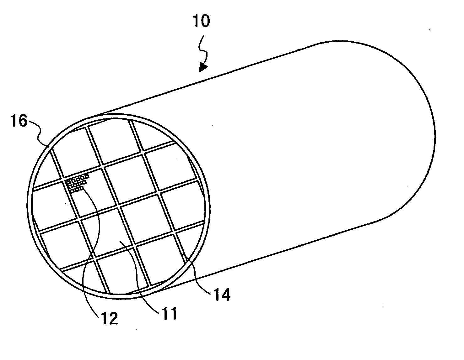
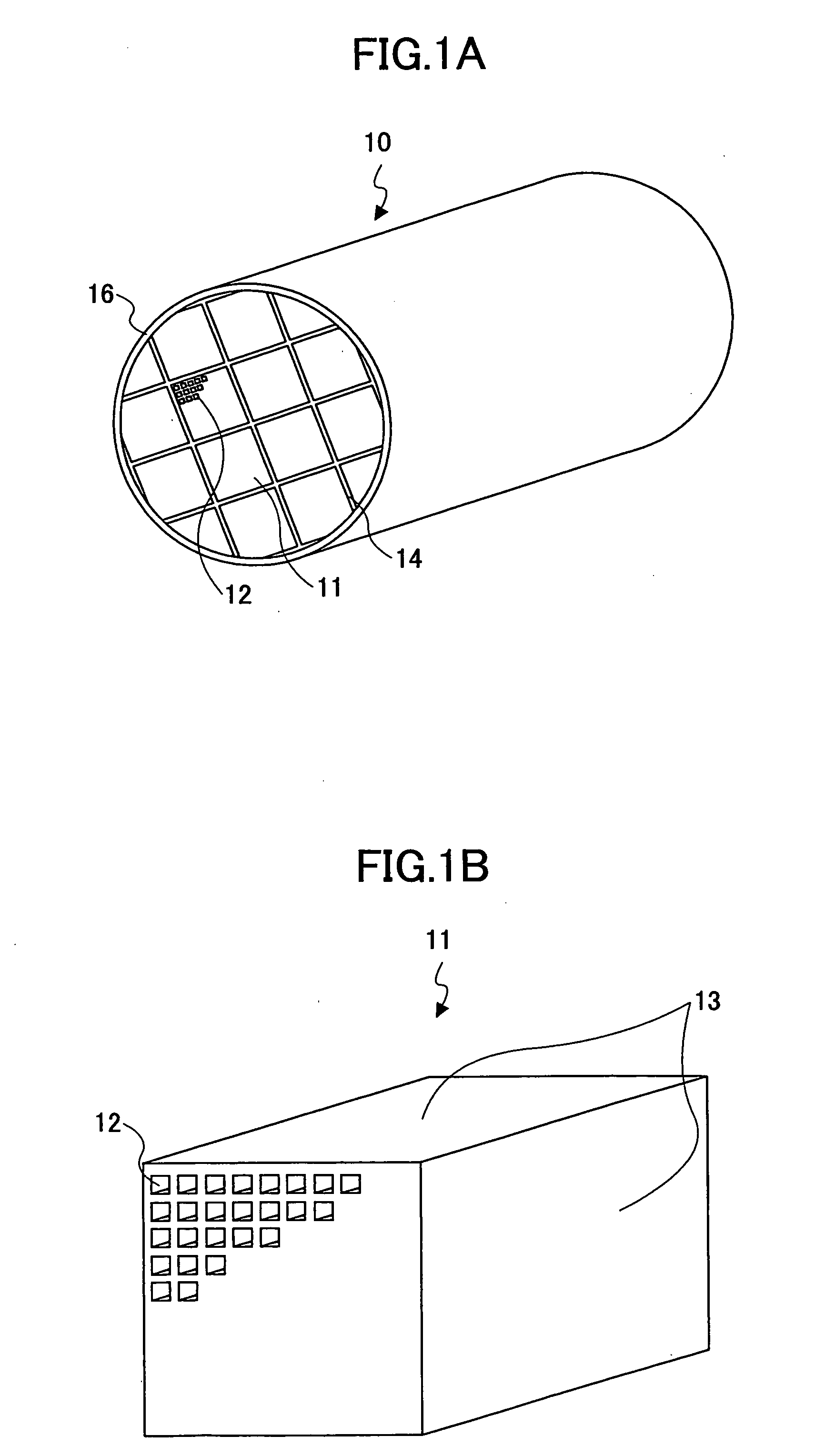
[0053] First, 40 wt % of γ-alumina particles (2 μm in average particle size), 10 wt % of silica-alumina fibers (10 μm in average fiber diameter, 100 μm in average fiber length, and of an aspect ratio of 10), and 50 wt % of silica sol (of a solid concentration of 30 wt %) were mixed. Six parts by weight of methylcellulose as an organic binder was added, together with small amounts of a plasticizer and lubricant, to 100 parts by weight of the obtained mixture. The mixture was further mixed and kneaded, so that a mixture composition was obtained. Next, the mixture composition was subjected to extrusion molding by an extruder, so that crude molded bodies were obtained.
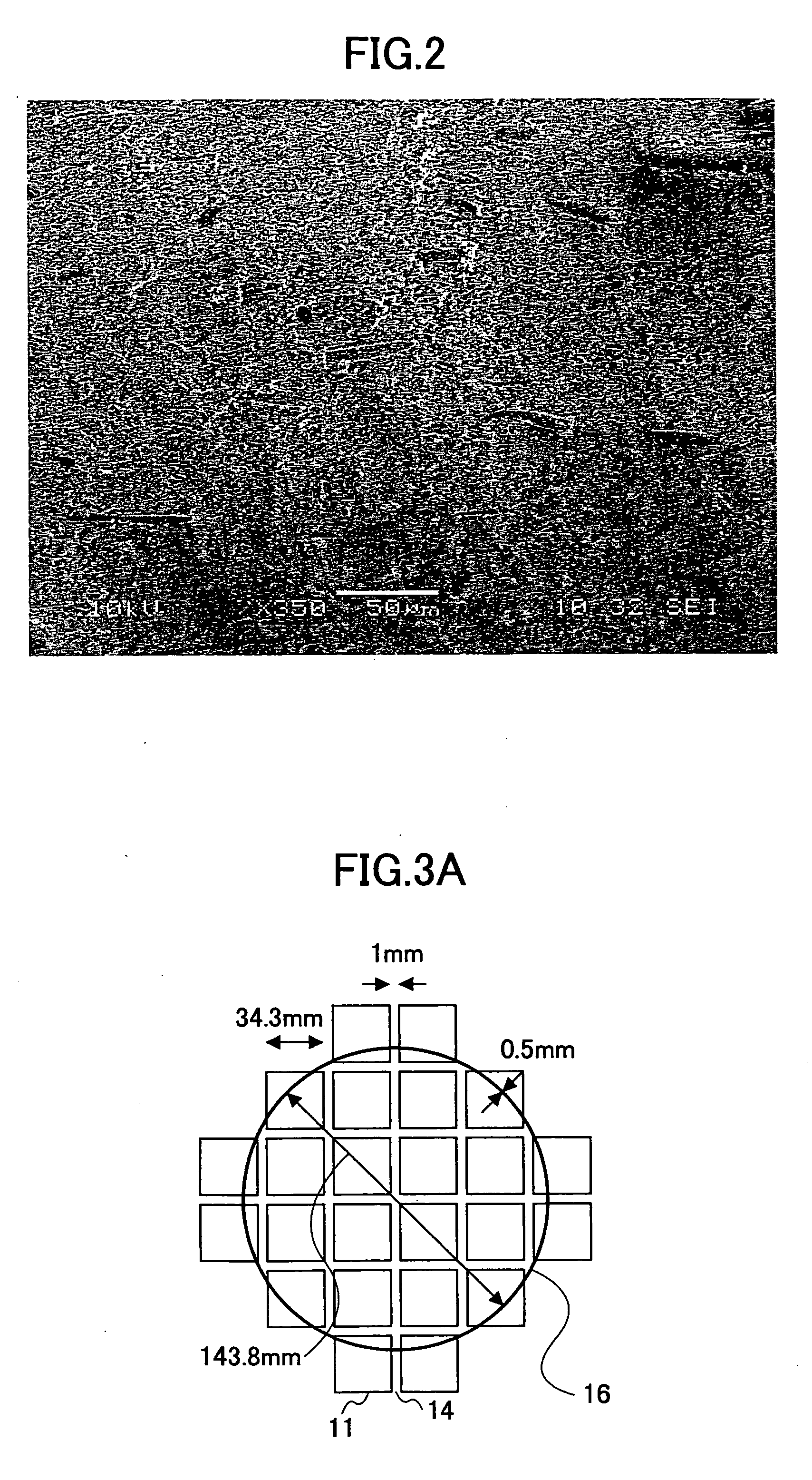
[0054] The crude molded bodies were sufficiently dried using a microwave drier and a hot air drier, and were degreased, being heated at 400° C. for 2 hours. Thereafter, the molded bodies were subjected to firing, being heated at 800° C. for 2 hours. As a result, the honeycomb units 11 each having a prism-like shape (34.3 ...
examples 2 through 7
[0059] The honeycomb structures 10 were made in the same manner as in Example 1 except that the honeycomb units 11 were made into respective shapes shown in Table 1. The shapes of the joint bodies of Examples 2, 3, and 4 are shown in FIGS. 3B, 3C, and 3D, respectively, and the shapes of the joint bodies of Examples 5, 6, and 7 are shown in FIGS. 4A, 4B, and 4C, respectively. In Example 7, the honeycomb structure 10 was monolithically formed, and accordingly, the joining process and the cutting process were not performed.
examples 1-a through 1-e
[0060] The honeycomb structures 10 in which the thermal conductivity of the seal material layer 14 was varied from 0.05-5.0 W / m·K were made (Examples 1-A through 1-E). The thermal conductivity was controlled using seal material pastes different in the material and / or compounding ratio of ceramic particles, the material and / or compounding ratio of inorganic fibers, and / or the compounding ratio of additives. In Examples 1-A through 1-E, those other than the seal material, such as the composition and the shape of the honeycomb units 11, were prepared in the same manner as in Example 1. Table 4 shows the component mixture ratios used for the seal material pastes of Examples 1-A through 1-E and the thermal conductivities of the seal materials prepared using these seal material pastes.
TABLE 4CERAMIC PARTICLESINORGANIC FIBERSSiCSiCSILICA-ALUMINAALUMINA FIBERSSiC FIBERSγ-ALUMINAPARTICLESPARTICLESFIBERS (10 μm(10 μm IN(10 μm INPARTICLES (2 μm(30 μm IN(0.5 μm ININ FIBER DIAMETER,FIBER DIAME...
PUM
 Abstract
Description
Claims
Application Information
 - R&D
- Intellectual Property
- Life Sciences
- Materials
- Tech Scout
- Unparalleled Data Quality
- Higher Quality Content
- 60% Fewer Hallucinations
Browse by: Latest US Patents, China's latest patents, Technical Efficacy Thesaurus, Application Domain, Technology Topic, Popular Technical Reports.
© 2025 PatSnap. All rights reserved.Legal|Privacy policy|Modern Slavery Act Transparency Statement|Sitemap|About US| Contact US: help@patsnap.com


