Corrugated steel deck system including acoustic features
- Summary
- Abstract
- Description
- Claims
- Application Information
AI Technical Summary
Benefits of technology
Problems solved by technology
Method used
Image
Examples
example 1
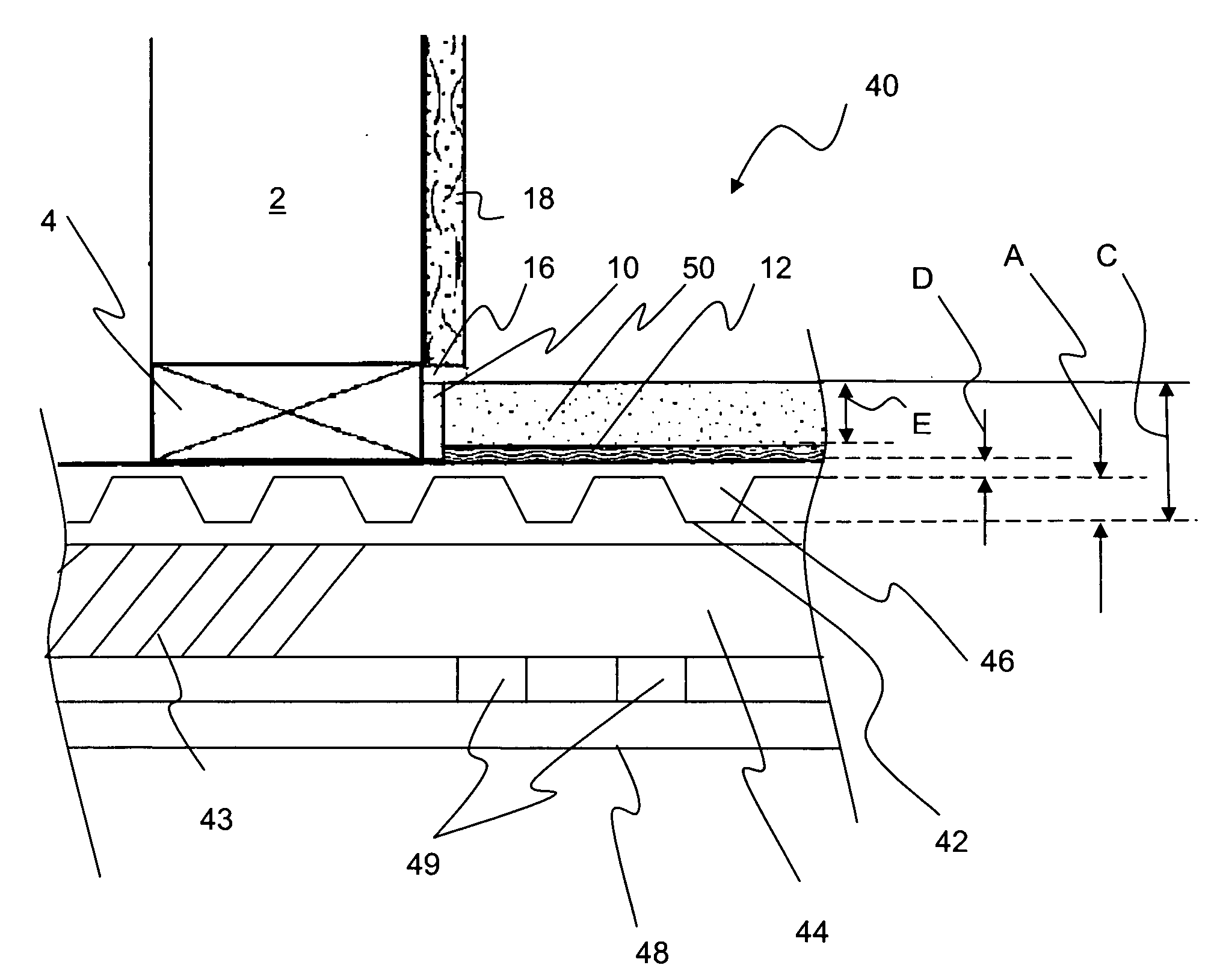
[0126] Tests were conducted according to ASTM C627-93 (1999) to determine the serviceability of the proposed invention. In these tests, floors were constructed using corrugated steel deck placed over wood joists. In the first tests two samples were conducted using no sound mat with the flooring material (LEVELROCK BRAND FLOOR UNDERLAYMENT CSD) placed either ¾ or 1 in. above the flutes of the corrugated steel deck. A second set of samples were constructed including sound mats. In these samples LEVELROCK BRAND CSD was placed in the flutes. The sound mat (SRM-25 Brand sound reduction mat) was then placed on the flutes and a layer of LEVELROCK BRAND FLOOR UNDERLAYMENT 3500 was placed over the mat at either ¾ or 1 in. thickness. Prior to testing all four systems were tiled using 2×2 in. ceramic tiles.
[0127] All 4 systems failed at cycle 6, demonstrating that the performance of the systems with and without the sound mats were similar.
[0128] Similar tests were also conducted to those des...
example 2
[0131] Tests were conducted in a standard acoustic chamber according to ASTM E90 and ASTM E492 to determine the STC and IIC performance of various floors.
[0132] Tests were conducted on two invention floors that differed by the type of ceiling assembly. To determine the improvement of the invention over current practice in which no acoustical mat is embedded, floors without acoustical mats were also tested.
[0133] In general, floor / ceiling assemblies for the invention were constructed using lightweight steel C-joists, corrugated metal pans, and LEVELROCK Brand FLOOR UNDERLAYMENT CSD. Tests for the invention included 1 in. of LEVELROCK BRAND CSD placed over SRM-25 sound mat. This was placed over a layer of LEVELROCK BRAND CSD that filled the flutes of the 22 gage, 9 / 16 in. corrugated metal deck. Two ceiling assemblies were evaluated. The first used USG DWSS Grid system suspended with Prototype acoustical clips spaced 48″ o.c. The second used the same ceiling system, without the proto...
example 3
[0178] Small scale tests were conducted to determine the acoustic properties of flooring systems constructed using leveling boards placed over 9 / 16 in. corrugated steel decks. Four samples (4×4 ft) were constructed. These small sections of floors were then placed on an existing floor-ceiling assembly.
[0179] This assembly consisted of the following (top down):
[0180] 2-¼″×2-¼″ Mosaic Ceramic Tiles adhered to NobleSeal Brand CIS crack isolation sheet with a standard thin-set mortar and grouted. The Noble CIS was adhered to the ¾″ LEVELROCK Brand floor underlayment with Noble 21 Brand adhesive. The LEVELROCK Brand floor underlayment was poured over a ⅜″ thick sheet of USG SRB Brand sound reduction board, which was loose laid over nominal ¾″ OSB panels. The OSB was screw attached to 9-½″ Wood I-Joists that were spaced 24″ o.c. Resilient channels (RC-1 Deluxe) were screw attached to the lower flange of the I-Joist at 16″ o.c. and 3-½″ R-11 glassfiber insulation was placed in the joist c...
PUM
 Abstract
Description
Claims
Application Information
 - R&D
- Intellectual Property
- Life Sciences
- Materials
- Tech Scout
- Unparalleled Data Quality
- Higher Quality Content
- 60% Fewer Hallucinations
Browse by: Latest US Patents, China's latest patents, Technical Efficacy Thesaurus, Application Domain, Technology Topic, Popular Technical Reports.
© 2025 PatSnap. All rights reserved.Legal|Privacy policy|Modern Slavery Act Transparency Statement|Sitemap|About US| Contact US: help@patsnap.com


