Method and apparatus for measuring high-bandwidth electrical signals using modulation in an optical probing system

a high-bandwidth electrical signal and modulation technology, applied in the direction of optical radiation measurement, light polarisation measurement, instruments, etc., can solve the problems of user burden, additional setup, difficult optimization of this algorithm, etc., and achieve high temporal resolution

Active Publication Date: 2007-01-04
DCG SYST
View PDF7 Cites 44 Cited by
  • Summary
  • Abstract
  • Description
  • Claims
  • Application Information

AI Technical Summary

Benefits of technology

[0020] Various embodiments of the present invention provide apparatus and method for laser probing of a DUT at very high temporal resolution, while enabling use of a conventional tunable or continuous wave (CW) laser source.

Problems solved by technology

This is a burden to the user because it prevents the user from testing at arbitrary clock frequencies and it requires additional setup by the user.
Optimizing this algorithm is difficult.
From the economic perspective, the MLL is expensive, and custom electronics and software must be developed.
All these custom elements increase the complexity and the overall cost of the system.
A major difficulty encountered by all laser-base probe systems is deciphering the weak modulation in the reflected signal, which is caused by the response of the DUT to the stimulus.
Another difficulty is noise introduced into the signal by the DUT's vibrations.
Consequently, the signal strength may be too weak for pure amplitude detection.
While this arrangement helps detect phase variations caused by the DUT, using this optical arrangement exposes the system to additional noise source from phase variations caused by DUT vibrations.
Moreover, since the beam needs to be placed at various locations in the chip, the system needs to be designed so that the beam separation is adjustable, which complicates the optics design.
Due to variations in the layout and dimensions of the DUT, it is difficult to find identical structures for probing within the range of adjustment of the two laser beams.
Since the two beams traverse a common path, DUT vibrations largely modulate both identically, making this scheme inherently vibration insensitive.
However, the optics required to generate the delay, and then reverse its effect for the reflected beams, are relatively complicated.
This can limit the maximum time span of a sampling window that can be used, or may require additional acquisition time to fill the desired sampling window with enough density of sampling points.
In addition, the temporal resolution (or measurement bandwidth) of this scheme is limited by the pulse separation used instead of by the width of the laser pulses.
Since larger pulse separations typically give better signal strength, this scheme suffers from a measurement bandwidth versus signal strength trade-off.
In addition to the difficulties introduced by the faint signal, another difficulty is caused by the advancement of the clock signal of modern circuits.
Consequently, while cost and operations considerations dictate for simplifying the system and preferably simplifying the laser source, the high frequency operation of the modern circuit dictate for even higher complexity.

Method used


Image

  • Method and apparatus for measuring high-bandwidth electrical signals using modulation in an optical probing system
  • Method and apparatus for measuring high-bandwidth electrical signals using modulation in an optical probing system
  • Method and apparatus for measuring high-bandwidth electrical signals using modulation in an optical probing system

Examples


Embodiment Construction

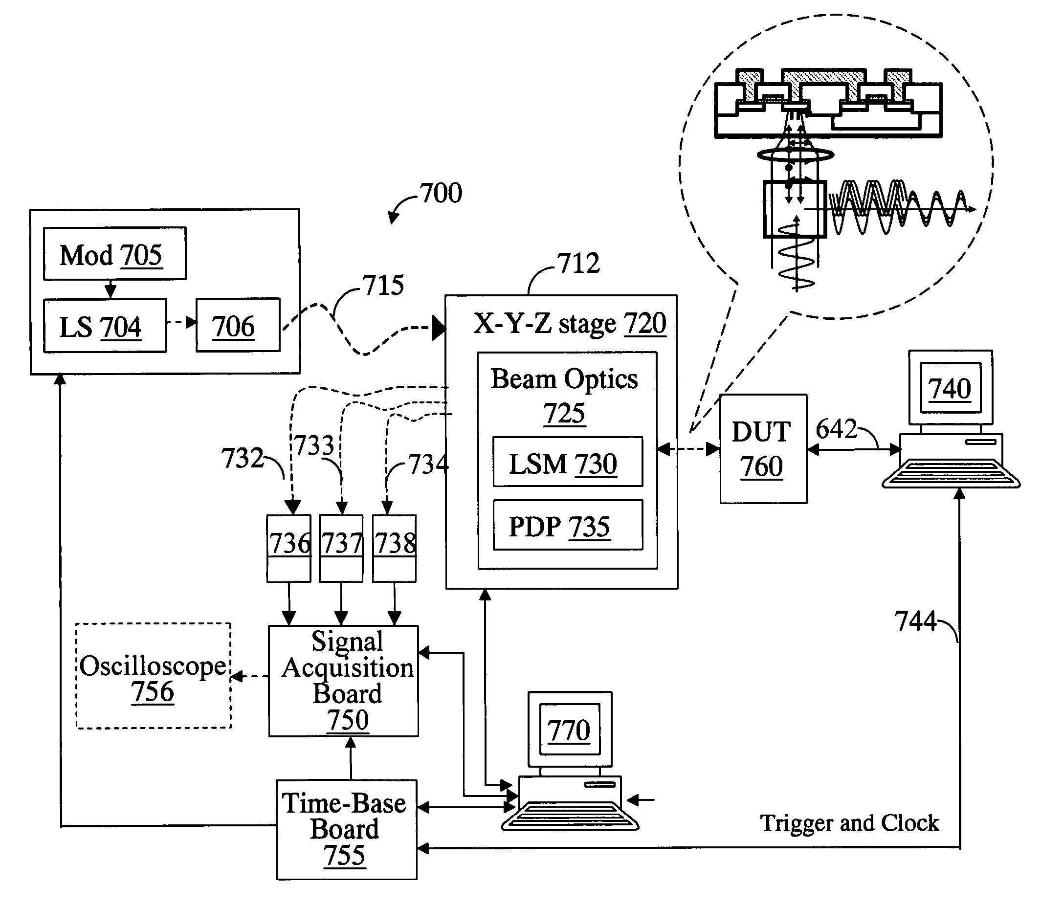
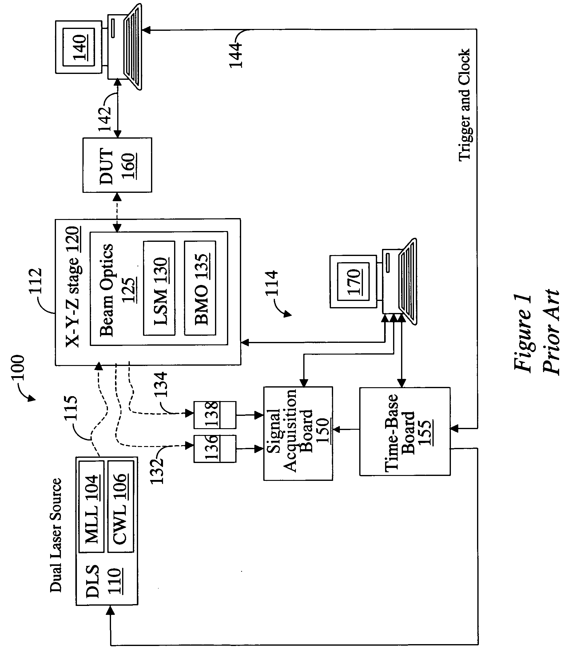
[0049] Various embodiments of the present invention provide apparatus and method for high bandwidth electrical signals using modulated laser in an optical probing system. These embodiments simplify the prior art system by eliminating the need for a mode-locked laser source. Consequently, the complexity and cost of the system is reduced, while its operation is simplified and adaptable to various testing environments. On the other hand, the embodiments enable probing of modern circuit devices operating at high frequencies.

[0050] An embodiment of the invention will now be described in details with reference to FIG. 6. Most notably, in this embodiment of the invention, a tunable or continuous wave (CW) laser source LS 604 is used, rather than the pulsed mode-locked laser source of the prior art. Using a CW laser source, such as a conventional tunable laser diode, reduces the overall cost and complexity of the system. Of course, as noted above, for laser probing of today's integrated ci...


PUM


Abstract

A system for probing a DUT is provided, the system comprising a tunable or CW laser source, a modulator for modulating the output of the laser source, a beam optics designed to point a probing beam at a designated location on the DUT, optical detector for detecting the reflected beam, and collection and signal processing electronics. The system deciphers perturbations in the reflected beam by detecting beat frequency between operation frequency of the DUT and frequency of the modulation. In an alternative embodiment, the laser is CW and the modulation is applied to the optical detector.

Description

CROSS-REFERENCE TO RELATED APPLICATION [0001] This application is a continuation-in-part of, and claims the benefit of priority from, U.S. patent application Ser. No. 11 / 169,423, filed on Jun. 29, 2005, the entire disclosure of which is relied upon and incorporated by reference herein. This application is also a continuation-in-part of, and claims the benefit of priority from, U.S. patent application Ser. No. 11 / 261,996, filed on Oct. 27, 2005, which claims the benefit of priority from Provisional Patent Application No. 60 / 711,998 filed on Aug. 26, 2005, the entire disclosures of which are relied upon and incorporated by reference herein.BACKGROUND [0002] 1. Field of the Invention [0003] The present invention relates to an apparatus and method for probing integrated circuits using laser illumination. [0004] 2. Description of the Related Art [0005] Probing systems have been used in the art for testing and debugging integrated circuit (IC) designs and layouts. Various laser-based syst...

Claims


Application Information

Patent Timeline
Patent Type & Authority Applications(United States)
IPC IPC(8): G01B9/02
CPCG01R31/308
Inventor WOODS, GARYKASAPI, STEVENWILSHER, KENNETH
Owner DCG SYST
Why Eureka
Try Eureka