Trackable optical discs with concurrently readable analyte material

a technology of optical discs and analyte materials, applied in the field of optical disc design and manufacture, can solve the problems of affecting the correct affecting the accuracy of the operation of the reader, and the provision of data, so as to facilitate the centering of non-operational problems

Inactive Publication Date: 2007-01-04
VINDUR TECH
View PDF13 Cites 24 Cited by
  • Summary
  • Abstract
  • Description
  • Claims
  • Application Information

AI Technical Summary

Benefits of technology

[0034] In conjunction with the inverted discs of the present invention, these latter disc geometries allow the purposive, concurrent and discriminable detection of nonoperational structures on an inverted optical disc.
[0035] The present invention thus provides inverted optical discs, as above described, wherein the operational structure includes a wobble groove. According to the manufacturing process, the wobble “groove” is presented as a forward image in positive relief (process 1) or as a forward image in negative relief. The latter orientation facilitates centering of nonoperational structures, such as analyte-specific signal elements, over the structure tracked during reading. Nonoperational structures disposed confocally with and laser-proximal to disc's information layer are concurrently detectable with, and their signals discriminable from, the wobble groove.

Problems solved by technology

However, although optical disc readers possess the mechanical prerequisites for effective confocal laser microscopic scanning, operational requirements of existing disc readers present significant impediments to the successful detection and characterization of microscopic structures disposed upon the surface of an optical disc.
Although efficient, such standards make no provision for acquiring data from nonoperational structures disposed upon the disc.
For example, because the tracking structures are obligately embedded within the information layer of the disc, structures applied to the laser-proximal surface of the disc may interfere with detection of such operational structures, and thus interfere with correct operation of the reader.

Method used


Image

  • Trackable optical discs with concurrently readable analyte material
  • Trackable optical discs with concurrently readable analyte material
  • Trackable optical discs with concurrently readable analyte material

Examples


example 1

Manufacture of a Trackable, Forward Image Positive Relief Inverted Optical Disc Suitable for Analyte-Specific Assay

[0288] An unpunched father part containing an image of a CD-R format wobble groove, manufactured by Cinram (Anaheim, Calif.), was matrixed to form a CD-R mother part by standard procedures. Briefly, the electroforming was performed in a nickel sulfamate bath in an electroforming system manufactured by Digital Matrix, Inc. (Hempstead, N.Y.).

[0289] The mother part was cleaned, polished and punched, then used directly as a stamper to manufacture inverted discs having a forward image spiral groove with operational structures in positive relief. A NETSTAL molding machine, manufactured by Netstal Machinery Ltd. (Naefels, Switzerland), and a CD-R mold created by AWM, of Switzerland were used to generate the discs at EXIMPO S.R.O. (Prague, Czech Republic). The molding parameters of the injection molding machine were adjusted to facilitate high venting in the mold, to accurate...

example 2

Construction of an IgG-Specific Immunoassay Site on a Trackable Optical Disc

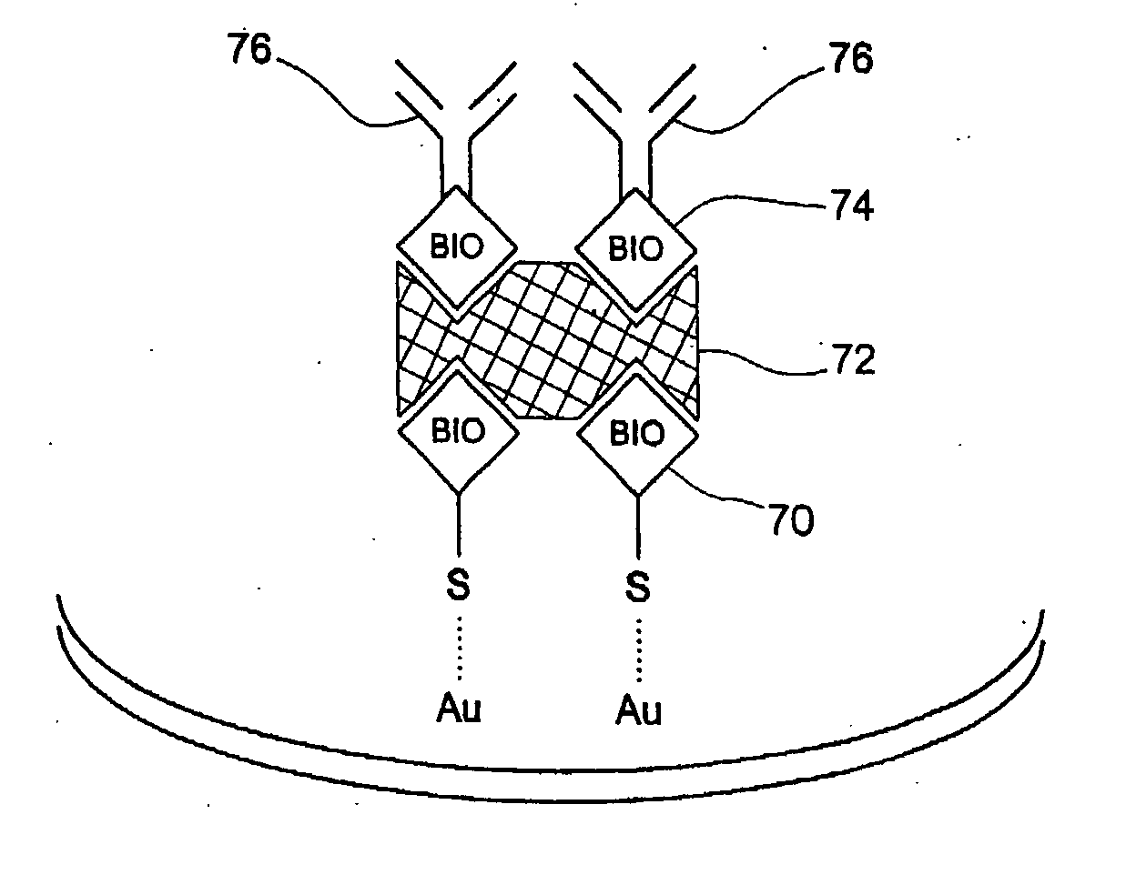
[0292] A single data layer, first surface, forward image / positive relief wobble disc was manufactured according to Example 1. The gold surface of the disc was then derivatized as follows to construct an assay site specific for and capable of detecting human IgG in a blood sample.

[0293] An aliquot of 2 mg of N-[6-(biotinamido)hexyl]-3′-(2′-pyridyldithio)propionamide (“Biotin-HPDP”) (Pierce, Rockford, Ill.; lot number 97032461) was dissolved in 2 ml of dimethylformamide. Onto each of four intended assay sites, each located at the same radius from the center of the disc, 10 μl of biotin-HPDP solution was pipetted. The disc was incubated for 2 hours at room temperature, and then washed with 50 mM phosphate buffer (pH 7).

[0294] Next, 10 μl of streptavidin solution (Monobind, Costa Mesa, Calif.; Lot 96-001 / MF; 2 mg / ml) was pipetted onto the same assay spots. The disc was incubated one hour at RT, and then washe...

example 3

Electronic Detection and Characterization of Human Erythrocytes on an RBC-Specific Trackable Immunoassay Optical Disc

[0303] A single data layer, first surface, forward image / positive relief wobble disc was manufactured according to Example 1. The gold surface of the disc Was then derivatized as follows.

[0304] An aliquot of 2 mg of N-[6(biotinamido)hexyl]-3′

[0305] t-(2′-Pyridyldithio)propionamide (“Biotin-HPDP”) (Pierce, Rockford, Ill., lot number 97033461) was dissolved in 2 ml of dimethylformamide. Onto each of four intended assay sites, each located at the same radius from the center of the disc, 10 μl of biotin-HPDP solution was pipetted. The disc was incubated for 2 hours at room temperature, and then washed with 50 mM phosphate buffer (pH 7).

[0306] Next, 10 μl of streptavidin solution (Monobind, Costa Mesa, Calif., Lot 96-001 / MF; 2 mg / ml) was pipetted onto the same assay spots. The disc was incubated one hour at RT, and then washed with 50 mM phosphate buffer.

[0307] Monoclo...


PUM

PropertyMeasurementUnit
depthaaaaaaaaaa
groove depthaaaaaaaaaa

Abstract

Optical discs for diagnostic purposes include analyte material and encoded information. The analyte material is analyzed or investigated by the read beam of an optical disc drive. Tracking is maintained so that encoded information may be read by the optical disc drive assembly.

Description

CROSS-REFERENCE TO RELATED APPLICATIONS [0001] This application is a divisional of commonly owned pending U.S. patent application Ser. No. 09 / 421,870, filed Oct. 26, 1999, which is a continuation-in-part of commonly owned U.S. patent application Ser. No. 09 / 311,329, filed May 11, 1999, which is a continuation-in-part of U.S. patent application Ser. No. 09 / 183,842, filed Oct. 30, 1998, now abandoned. This application also claims priority to U.S. Provisional Patent Application No. 60 / 134,368, filed May 14, 1999. The disclosures of each of the above-referenced applications are incorporated herein by reference in their entireties.FIELD OF THE INVENTION [0002] The present invention relates to the design and manufacture of optical discs and their use in optical disc readers and reader / writers. Specifically, the invention relates to the design, manufacture and use of optical discs that permit the concurrent and discriminable acquisition of signals from nonoperational structures of the disc...

Claims


Application Information

Patent Timeline
Patent Type & Authority Applications(United States)
IPC IPC(8): G01N33/53
CPCB01L3/502707B01L3/5088B01L2300/024B01L2300/046G01N2021/6439B01L2300/0654B01L2300/0806G01N21/645G01N35/00069B01L2300/0636
Inventor WORTHINGTON, MARK O.
Owner VINDUR TECH
Why Eureka
Try Eureka