Automated continuous operation tube forming system

a tube forming system and continuous operation technology, applied in the field of automatic continuous operation tube forming system, can solve the problems of preventing continuous use of wires, less efficiency and productivity of operation, and small gage size of wiring, so as to facilitate forming, minimize interference, and high efficiency and productivity

Inactive Publication Date: 2007-01-11
WEBSTER M CRAIG
View PDF10 Cites 27 Cited by
  • Summary
  • Abstract
  • Description
  • Claims
  • Application Information

AI Technical Summary

Benefits of technology

[0010] Such system according to the invention may also include one or more servo motors or other appropriate devices associated with each collet to rotate or otherwise move a workpiece as supported by the collet to thereby facilitate forming on multiple planes. Also, the workstations may each be capable of operation involving rotation or other movement in multiple directions to minimize the possibility of interference between the workpiece and the workstation.
[0011] Such tube forming system according to the invention is very advantageous because it can be fully automated and operated continuously and wirelessly to achieve a very high level of efficiency and productivity. For example, because all of the workstations are associated with a single carousel, the workstations are efficiently disposed within a very small area i...

Problems solved by technology

As will be understood, greater involvement of human operator(s) in a given tube forming operation, usually results in less efficiency and productivity for the operation.
Moreover, even if a tube forming operation is performed in an automated manner involving one or more machines, typically the machines have inherent limitations which prevent them from being used continuously.
Such wiring may be of very small gage-size because the s...

Method used


Image

  • Automated continuous operation tube forming system
  • Automated continuous operation tube forming system
  • Automated continuous operation tube forming system

Examples


Embodiment Construction

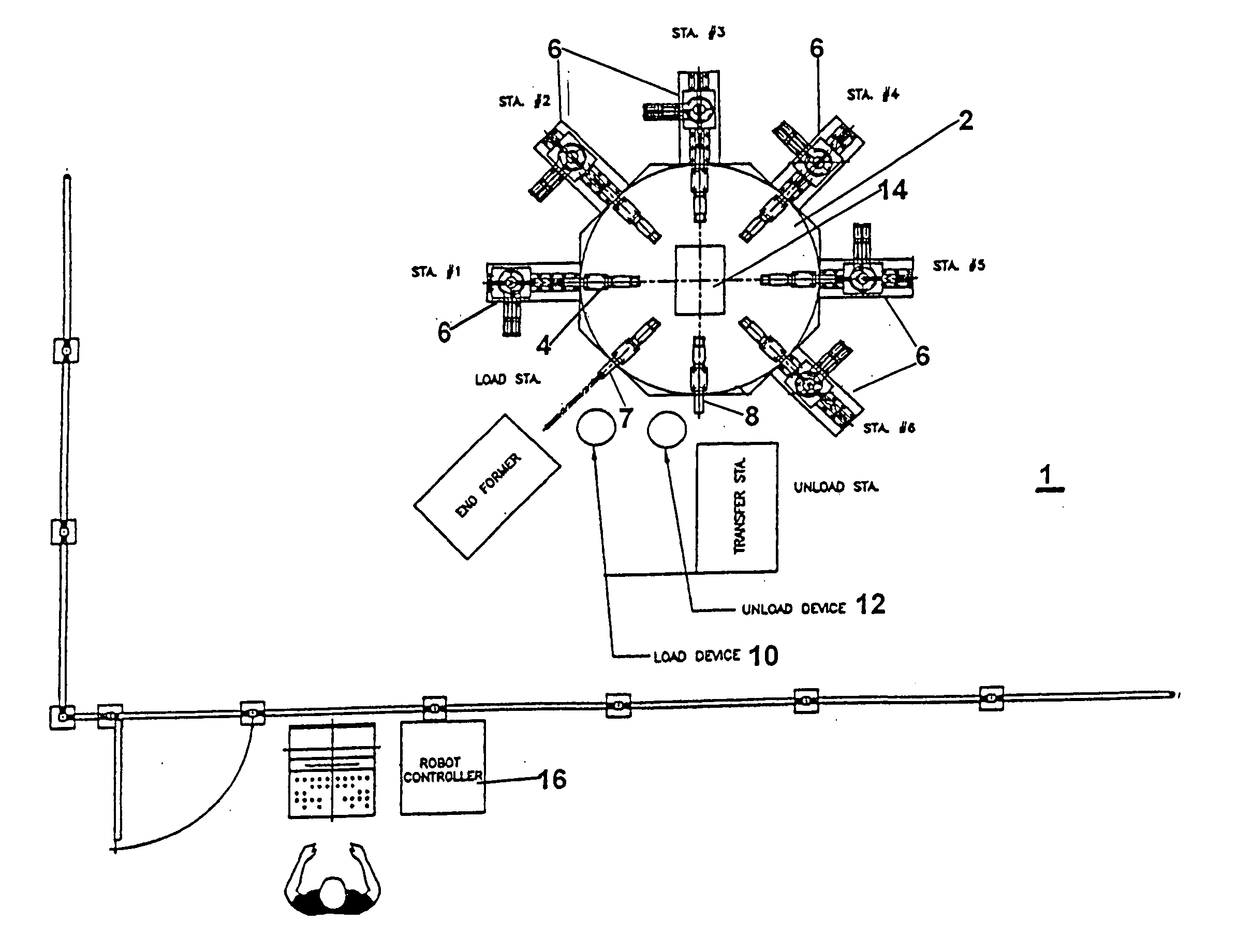
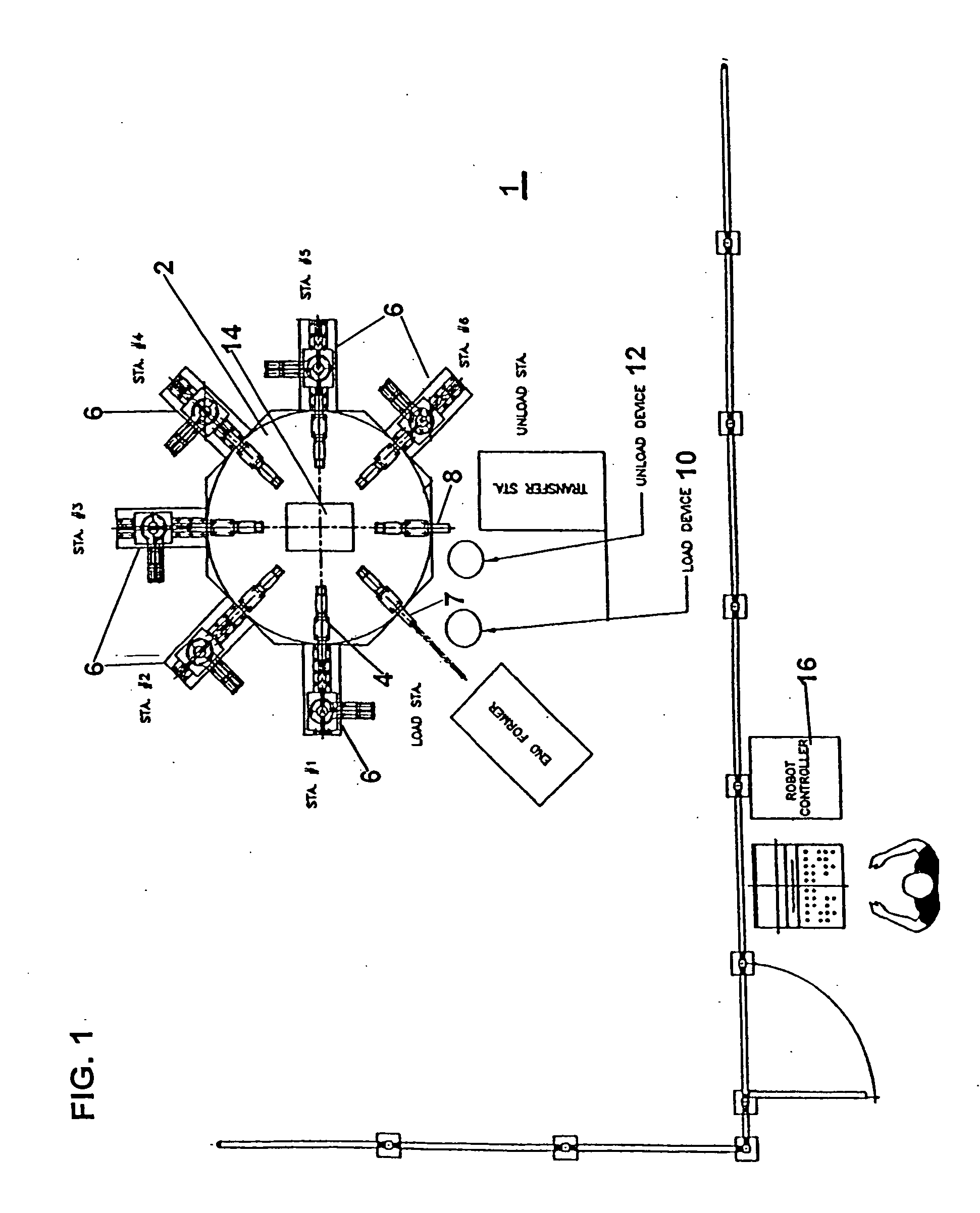
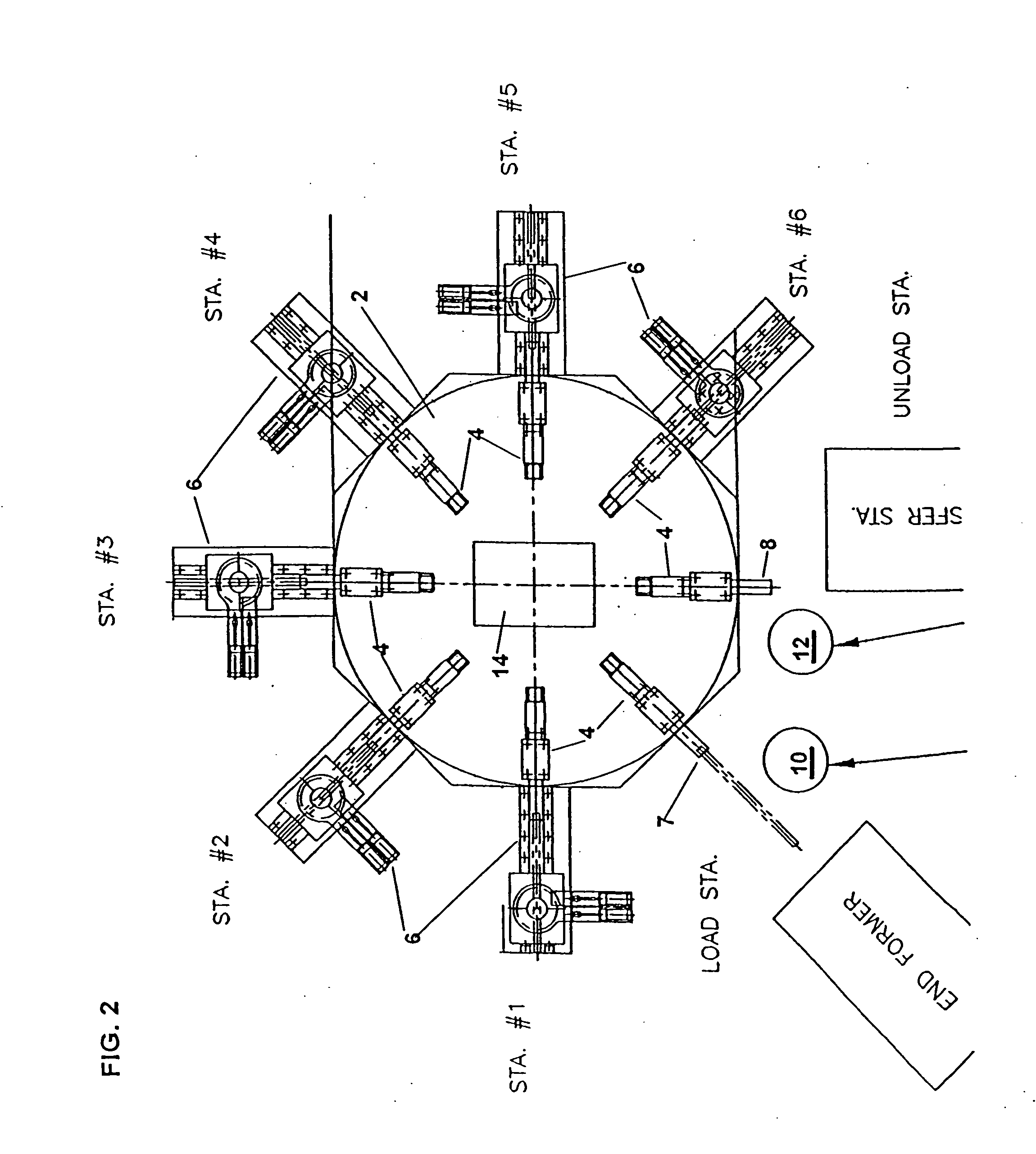
[0020] Referring to the drawings, an automated, wireless, continuous tube forming system according to the present embodiment of the invention is indicated at 1. The system 1 includes an indexing transfer carousel 2 having a plurality of workpiece-holding collets 4 provided thereon in a uniformly spaced manner around the periphery-circumference thereof, and which are adapted to support workpieces such as a length of tubing, a length of tubing with end fittings, etc. In the depicted embodiment, eight of the collets 4 are provided on the carousel which is octagonal in shape, although the invention is not limited to any particular number collets or carousel shape. Similarly, it is not essential for the collets to be uniformly spaced on the carousel 2, or for the workpiece to be a length of tubing.

[0021] The system 1 further includes a plurality of workstations 6 disposed around the periphery of the carousel 2 which will perform various operations on the workpieces when the workpieces a...


PUM

PropertyMeasurementUnit
Poweraaaaaaaaaa

Abstract

An automated, continuous tube forming system comprising: a plurality of workstations which respectively perform various operations on a workpiece; an indexing transfer carousel having a plurality of workpiece-holding collets provided in a spaced arrangement around the periphery-circumference of the of the carousel and which are adapted to support a plurality of workpieces, respectively, the multiple workstations are provided around the indexing transfer carousel and the carousel is selectively rotated to move the collet-supported workpieces such that the workpieces are associated with the workstations where various operations can be performed on the workpieces; a loading device which loads workpieces on the indexing transfer carousel; a transfer device which unloads the finished workpieces from the indexing transfer carousel after processed at the workstations; and a controller which controls operations of the indexing transfer carousel, the workstations, the loading device, and the transfer device. Electrical power may be provided to the indexing transfer carousel via a movable type power connector such as a slip-ring connector, operations of the indexing transfer carousel, the workstations, the loading device, and the transfer device are continuously monitored using appropriate sensors, and the sensors communicate with the controller via wireless communication signals such as RF signals.

Description

BACKGROUND OF THE INVENTION [0001] 1. Field of the Invention [0002] The present invention relates to an automated tube forming system and method, and more particularly to such a system and method with significantly increased productivity of parts because the system can be run continuously and wirelessly without human operators, and within a significantly reduced space. [0003] 2. Description of the Background Art [0004] There are many known systems and methods for tube forming, including systems and methods which are partially or fully automated. Typically, a tube forming operation may involve multiple processing steps for the tubing, e.g., steps of bending (compression, draw, mandrel, non-mandrel), drilling, sizing (expanding or reduction), cutting (shear, laser, plasma), notching, etc. Typically at least some of the various operations are performed using different machines located separately from each other, so that the tubing being formed is moved between the different machines-lo...

Claims


Application Information

Patent Timeline
IPC IPC(8): B23P21/00B23Q15/00
CPCB23P21/006Y10T29/53048Y10T29/53061Y10T29/53052Y10T29/53039
Inventor WEBSTER, M. CRAIG
Owner WEBSTER M CRAIG
Why Eureka
Try Eureka