Non-volatile memory with asymmetrical doping profile

a technology of asymmetric doping and non-volatile memory, applied in the direction of electrical devices, semiconductor devices, instruments, etc., can solve the problems of reducing boosting potential, unselected memory cells, and inadvertent programming of same word lines, so as to reduce the short channel effect, shorten the channel, and induce the effect of boosting

Inactive Publication Date: 2007-01-18
WODEN TECH INC
View PDF36 Cites 23 Cited by
  • Summary
  • Abstract
  • Description
  • Claims
  • Application Information

AI Technical Summary

Benefits of technology

[0036] An asymmetrical memory cell doping profile in which the source side and the drain side of the memory cells are doped differently optimizes a balance between boosting induced drain leakage and the short channel effect. To reduce the short channel effect, a B-Halo type of implantation with a relatively high dose is used at the source side of the memory cell. At the drain side of the cell, no B-Halo is implanted at all or only a relatively low B-Halo dose is implanted. At the source side of the cell, a relatively high dose n-type implantation is used to create the source since the n-type implantation should result in a higher concentration than the B-Halo that is also implanted in the same area. Furthermore, the n-type area can be created in such a way that the floating gate overlaps the source n-type area to a certain extend to ensure that electrons from the source area can flow to the channel area under the floating gate without experiencing too large of a series resistance that could be caused by insufficient overlap of the floating gate and source. At the drain side of the cell, a lower dose n-type implantation can be used since because of the lower Boron concentration at the drain side, a lower n-type dose is sufficient to create an overlap of the floating gate with the drain area. It is even possible to reduce the effective Boron concentration, or more accurately, reduce the effective p-type concentration, at the drain side by implanting a low dose n-type counter implantation that compensates part of the boron at the drain side. Such a counter implantation could for example be done with Phosphorus but can also be done with an Arsenic implantation having a higher energy (and lower dose) than normally used in a drain / source type of implantation. The above memory cell can have good short channel properties and a sufficiently high threshold voltage, while at the same time have good boosting induced drain leakage properties. The short channel characteristics are mainly determined by the B-Halo implantation at the source side of the memory cell, while the boosting induced drain leakage characteristics are mainly determined by the doping profile at the drain side of the memory cell. The doping profile at the drain side can be made less steep than at the source side because both the p-type and n-type doping concentrations at the drain side can be lower.

Problems solved by technology

A problem arises when it's desired to program one cell on a word line without programming other cells connected to the same word line, for example, when it's desired to program memory cell 224 and not memory cell 244.
Because the program voltage is applied to all memory cells connected to a word line, an unselected memory cell (a memory cell that is not to be programmed) on the same word line may become inadvertently programmed.
Because of this negative charge on the floating gates, the boosting potential is reduced and there still may be program disturb on the last few word lines.
This problem is exacerbated for multi-level memory cells since the programmed threshold voltage can be higher for multi-level memory cells, resulting in less boosting.
Although the two channel areas are separated by the word line connected to zero volts, this does not mean that the isolation between the two areas is perfect.
This will become especially more severe for future generation NAND devices since the channel lengths will become shorter and, thus, punch-through can occur at lower voltage differences.
Furthermore, breakdown or leakage at the bottom of the drain junction (drain to P-well) may occur as well.
Due to the vertical electric field discussed above, or due to the combination of a strong lateral and vertical field, there is a breakdown causing leakage.
The leakage of electrons to boosted channel 470 can cause the boosted voltage to leak away prematurely, resulting in program disturb.
The injection of hot holes or electrons may cause undesired threshold voltage shifts in the memory cells, thus, causing program disturb or the gate oxides of the memory cells maybe degraded by the hot carriers causing other reliability problems.
As the electric field increases, the chance that boosting induced drain leakage will occur increases as well.
On the other hand, too much P-type material could cause boosting induced drain leakage due to an increased electric field around or in the drain.
This is undesired as certain variations in channel length are expected due to variations in the production process.
A disadvantage of using a B-Halo type of structure for the memory cells, however, is that the transition from N-type to P-type material is steep since both a P-type and N-type material are implanted in the same area with relatively high doses.
This steep doping profile may increase the boosting induced drain leakage due to the increased electric field around and in the drain, and therefore, result in degraded program disturb behavior.
Even when the B-Halo technique is not used, scaling devices requires a higher P-type concentration in the channel area of the memory cells to avoid punch-through during boosting or threshold voltage variations during read (short channel effect), which will also result in increased electric field strengths around or in the drain and therefore increase the probability of boosting induced drain leakage.
Thus, the requirements for scaling the memory cell and reducing boosting induced drain leakage are conflicting.
As a result, scaling the memory cells can result in an increase in boosting induced drain leakage, and program disturb may deteriorate with each process generation.

Method used


Image

  • Non-volatile memory with asymmetrical doping profile
  • Non-volatile memory with asymmetrical doping profile
  • Non-volatile memory with asymmetrical doping profile

Examples


Embodiment Construction

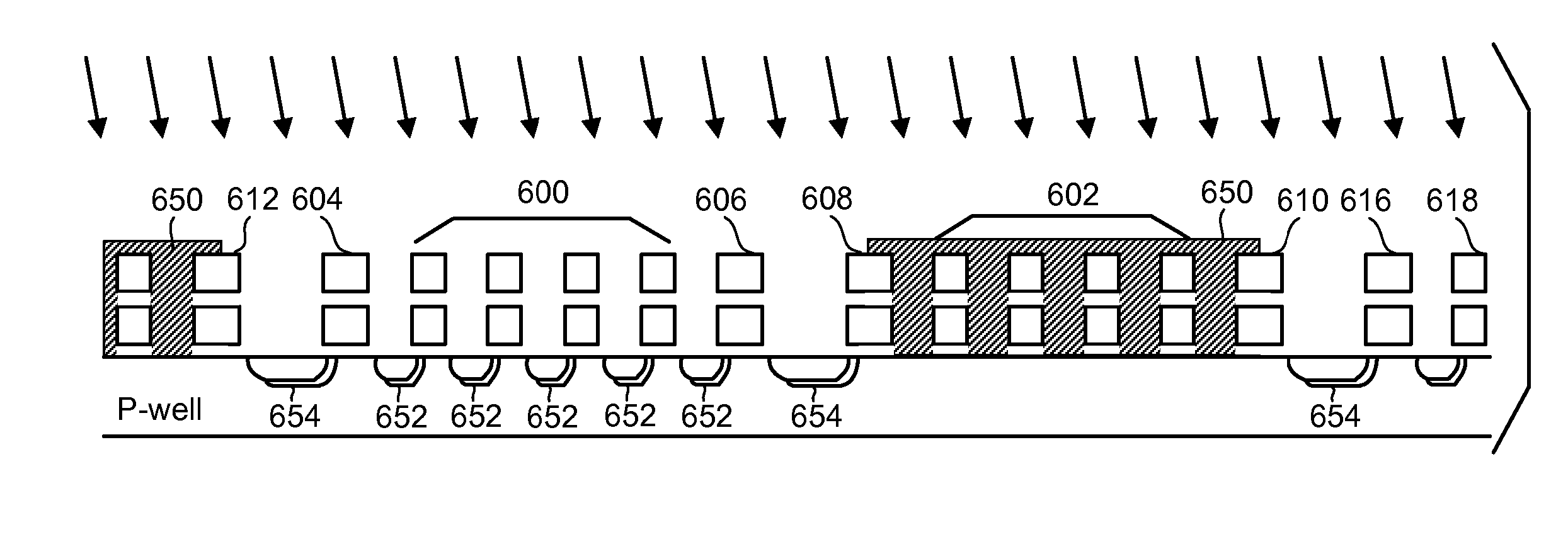
[0056] Scaling of the memory cell dimensions is possible while not necessarily degrading the boosting induced drain leakage behavior of the memory cell by using an asymmetrical memory cell doping profile in which the source side and the drain side of the memory cells are doped differently, and / or the channel is doped asymmetrical. FIGS. 8A-E provide a number of embodiments of such a memory cell.

[0057] The structure of FIGS. 8A-E includes a P-type substrate (e.g., Silicon), an N-well within the substrate and a P-well within the N-well (all of which are not depicted to make the drawings more readable). Note that the P-well may contain a so called channel implantation that is usually a P-type implantation that determines or helps to determine the threshold voltage and other characteristics of the memory cells. FIGS. 8A-E show three stacked gate structures 480A, 480B and 480C that are formed on the top surface of the P-well. The stacked gate structures are part of a NAND string. The st...


PUM


Abstract

Stacked gate structures for a NAND string are created on a substrate. Source implantations are performed at a first implantation angle to areas between the stacked gate structures. Drain implantations are performed at a second implantation angle to areas between the stacked gate structures. The drain implantations create lower doped regions of a first conductivity type in the substrate on drain sides of the stacked gate structures. The source implantations create higher doped regions of the first conductivity type in the substrate on source sides of the stacked gate structures.

Description

CLAIM OF PRIORITY [0001] This application claims the benefit of and is a divisional of U.S. application Ser. No. 10 / 952,689, “Non-volatile Memory with Asymmetrical Doping Profile,” by Hemink, et al., filed Sep. 28, 2004, incorporated herein by reference.BACKGROUND OF THE INVENTION [0002] 1. Field of the Invention [0003] The present invention relates to a non-volatile memory cell with asymmetrical doping profile for source and drain regions. [0004] 2. Description of the Related Art [0005] Semiconductor memory devices have become more popular for use in various electronic devices. For example, non-volatile semiconductor memory is used in cellular telephones, digital cameras, personal digital assistants, mobile computing devices, non-mobile computing devices and other devices. Electrical Erasable Programmable Read Only Memory (EEPROM) and flash memory are among the most popular non-volatile semiconductor memories. [0006] Many types of EEPROM and flash memories utilize a floating gate t...

Claims


Application Information

Patent Timeline
Patent Type & Authority Applications(United States)
IPC IPC(8): H01L21/8238H01L21/336H01L21/425
CPCG11C16/0483G11C16/10H01L27/115H01L29/7885H01L27/11524H01L29/66825H01L27/11521H10B69/00H10B41/30H10B41/35
Inventor HEMINK, GERRIT JANSATO, SHINJI
Owner WODEN TECH INC
Why Eureka
Try Eureka