Liquid-metal cooled reactor equipped with alkali metal thermoelectric converter

a technology of liquid metal thermoelectric converter and thermoelectric converter, which is applied in nuclear reactors, greenhouse gas reduction, lighting and heating apparatus, etc., can solve the problems of difficult to ensure that the power generation efficiency significantly exceeds about 40%, and the alkali metal thermoelectric converter cannot become a power generation system comparable with the power generation efficiency of steam turbine power generation systems, etc., to achieve the reduction of the heat transfer area necessary for heat exchange, the effect of large heat transport volume and high heat transport volum

Inactive Publication Date: 2007-01-25
JAPAN ATOMIC ENERGY AGENCY INDEPENDANT ADMINISTRATIVE CORP
View PDF3 Cites 9 Cited by
  • Summary
  • Abstract
  • Description
  • Claims
  • Application Information

AI Technical Summary

Benefits of technology

[0015] Particularly, when a vapor supply type alkali metal thermoelectric converter which utilizes the evaporation and condensation of an alkali metal is used, a large heat transport volume can be obtained by utilizing the heat pipe function and a high heat transport volume per heat-receiving area becomes possible, with the result that the heat transfer area necessary for heat exchange can be decreased as compared to a conventional type heat exchanger.
[0016] Further, in a case where, as the alkali metal thermoelectric converter, there

Problems solved by technology

However, the power generation efficiency of an alkali metal thermoelectric converter which operates at about 500° C. to 700° C. or so, which are coolant temperatures of a liquid-metal cooled reactor, is not more than about 20%, and an alkali metal thermoelectric converter could not become a power generation system comparable with the power generation effi

Method used


Image

  • Liquid-metal cooled reactor equipped with alkali metal thermoelectric converter
  • Liquid-metal cooled reactor equipped with alkali metal thermoelectric converter
  • Liquid-metal cooled reactor equipped with alkali metal thermoelectric converter

Examples


Embodiment Construction

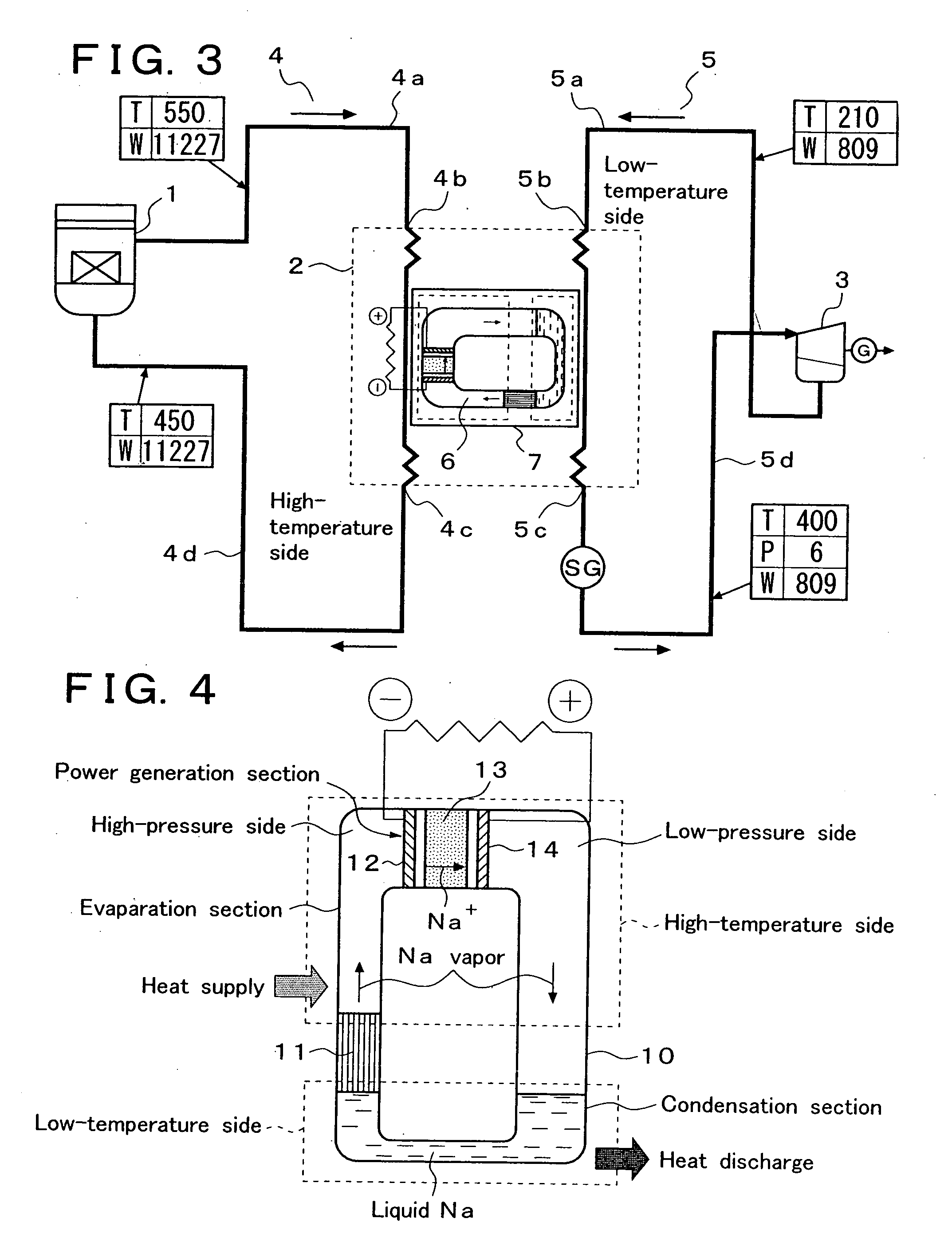
[0021] An alkali metal thermoelectric converter which can be used in the present invention is not especially limited so long as it is an alkali metal thermoelectric converter having the heat transport function. An alkali metal thermoelectric converter having a basic construction as shown in FIG. 4 and an alkali metal thermoelectric conversion cell of a compact construction as shown in FIG. 1 can be advantageously used.

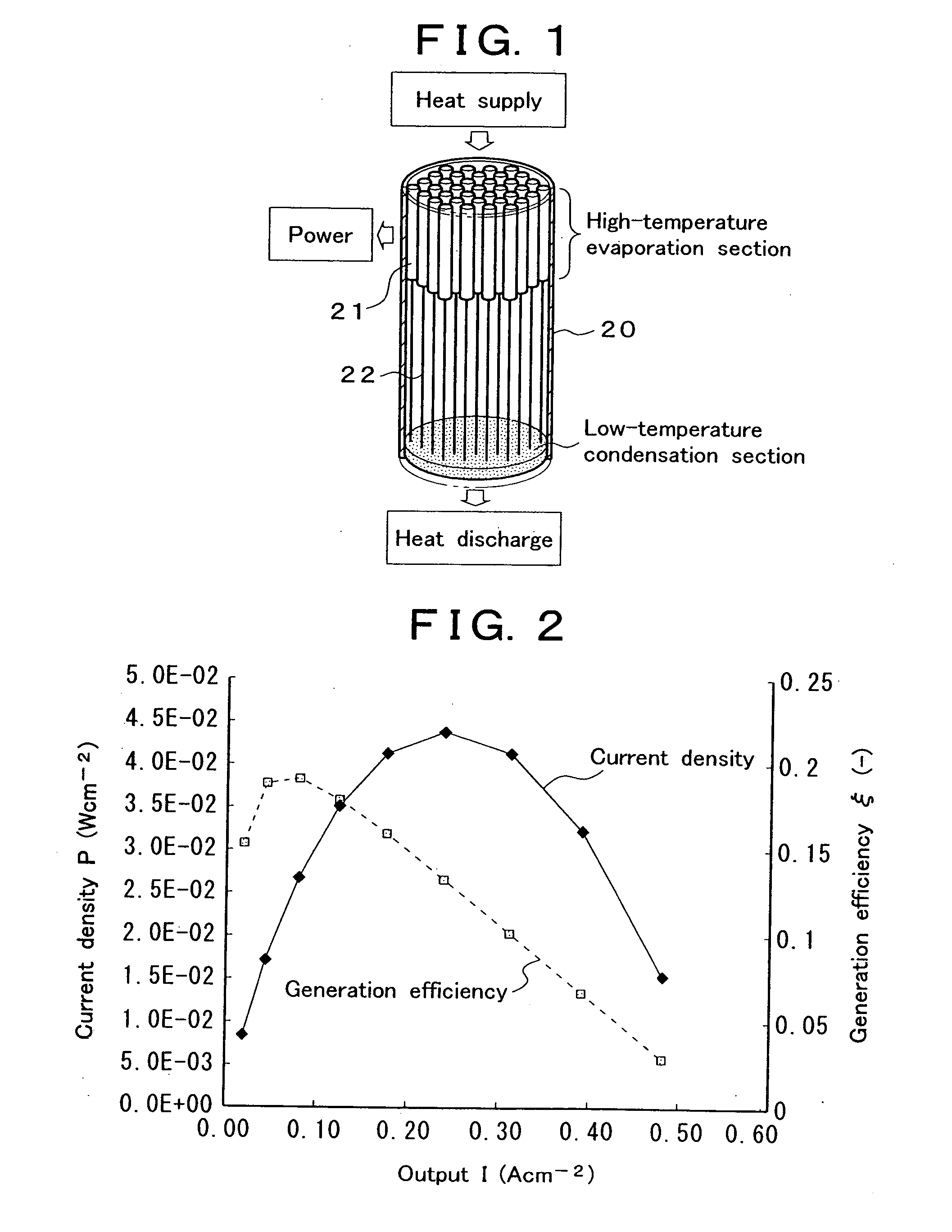
[0022] The cell structure of FIG. 1 will be described. In the interior of a hermetically-sealed cylindrical container 20 (for example, made of stainless steel, inside diameter: 30 mm, length: 75 mm), a high-temperature evaporation section which receives heat supply (for example, 500° C., which is the temperature of a liquid sodium coolant) is formed in an upper portion and a low-temperature condensation section which discharges heat (for example, 250° C.) is formed on a bottom surface. In the high-temperature evaporation section, a plurality of cylindrical power gener...


PUM


Abstract

In a liquid-metal cooled reactor equipped with a primary cooling system, a secondary cooling system and a steam turbine power generation system, or equipped with a primary cooling system and a steam power generation system, an alkali metal thermoelectric converter is disposed between the primary cooling system or the secondary cooling system and the steam turbine power generation system. Heat of the primary cooling system or the secondary cooling system is supplied to a high-temperature side of the alkali metal thermoelectric converter and waste heat on a low-temperature side of the alkali metal thermoelectric converter is supplied to the steam turbine power generation system. Thus, power generation by the steam turbine power generation system is performed simultaneously with power generation by the alkali metal thermoelectric converter. As a result, the power generation efficiency of the whole plant can be significantly increased.

Description

BACKGROUND OF THE INVENTION [0001] The present invention relates to a new and improved liquid-metal cooled reactor which is improved in power generation efficiency by incorporating an alkali metal thermoelectric converter having a heat transport function in a liquid-metal cooled reactor. [0002] An alkali metal thermoelectric converter is a type of concentration cell which performs power generation by giving a concentration difference (i.e., vapor pressure difference) of alkali metal vapor to both sides of a solid electrolyte, such as β″-alumina or the like, having alkali metal ion conductivity. Generators of various types of construction have hitherto been known and various proposals for improving these generators have also been made (for example, Japanese Patent Laid-Open No. 2005-39937, Japanese Patent Laid-Open No. 6-54566, Japanese Patent Laid-Open No. 6-163089, etc.). [0003] The principle of an alkali metal thermoelectric converter will be described by taking an alkali metal th...

Claims


Application Information

Patent Timeline
IPC IPC(8): H01L35/30
CPCG21C1/02G21D7/04G21Y2002/201Y02E30/34G21Y2004/30Y02E20/16G21Y2002/40F28D15/0266Y02E30/30Y02E30/00
Inventor NAKAGIRI, TOSHIOTANAKA, KOTAROHONDA, TAKEOFUJII, TAKAHIROAOTO, KAZUMI
Owner JAPAN ATOMIC ENERGY AGENCY INDEPENDANT ADMINISTRATIVE CORP
Why Eureka
Try Eureka