

Plasma source and plasma processing apparatus
a plasma processing and plasma technology, applied in the direction of chemistry apparatus and processes, electric discharge tubes, material nanotechnology, etc., can solve the problems of low plasma density, fast electrode consumption, and difficult to obtain sufficient ion flux, so as to achieve high-density plasma high efficiency
- Summary
- Abstract
- Description
- Claims
- Application Information
AI Technical Summary
Benefits of technology
Problems solved by technology
Method used
Image

Examples
example 1
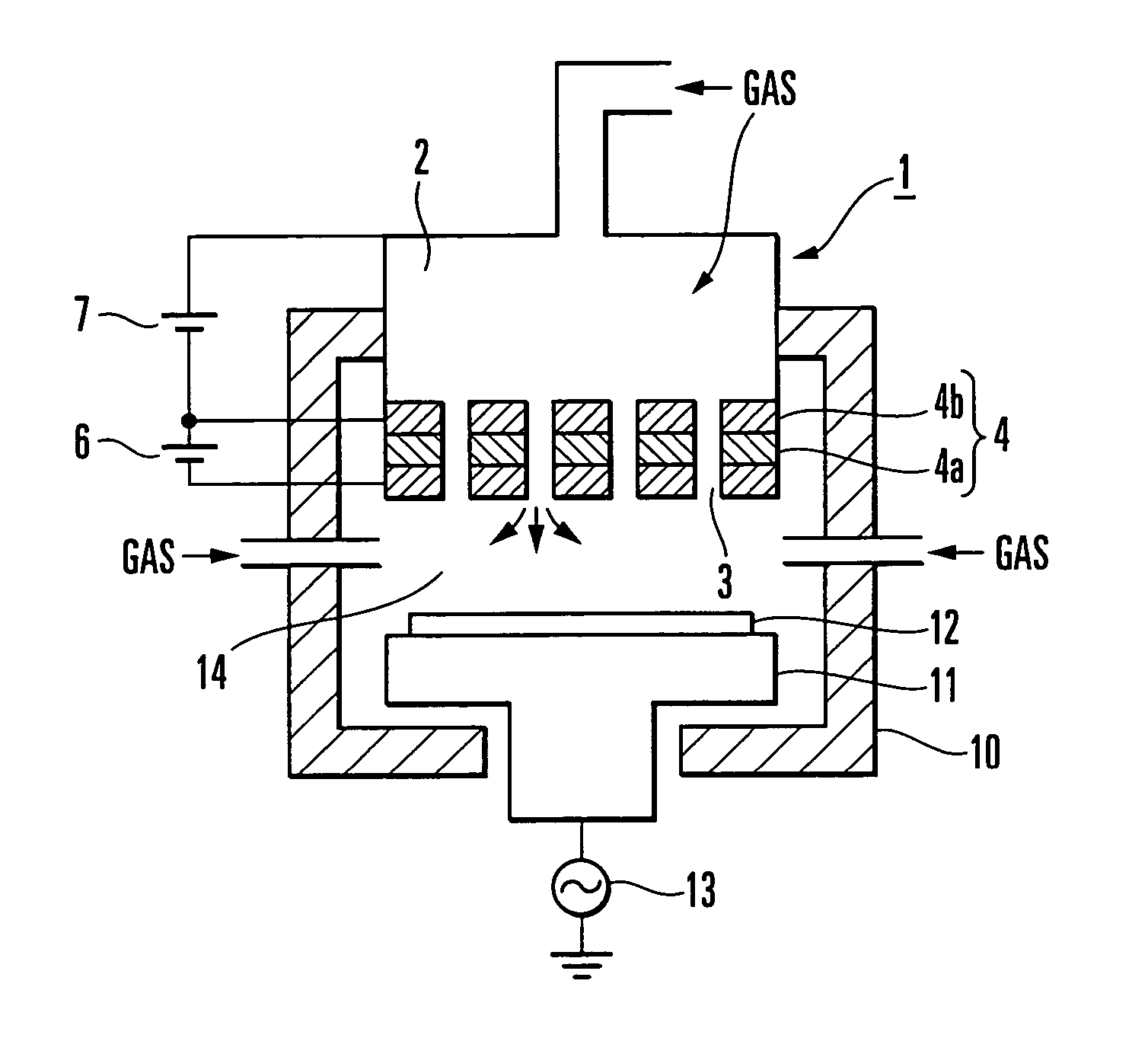
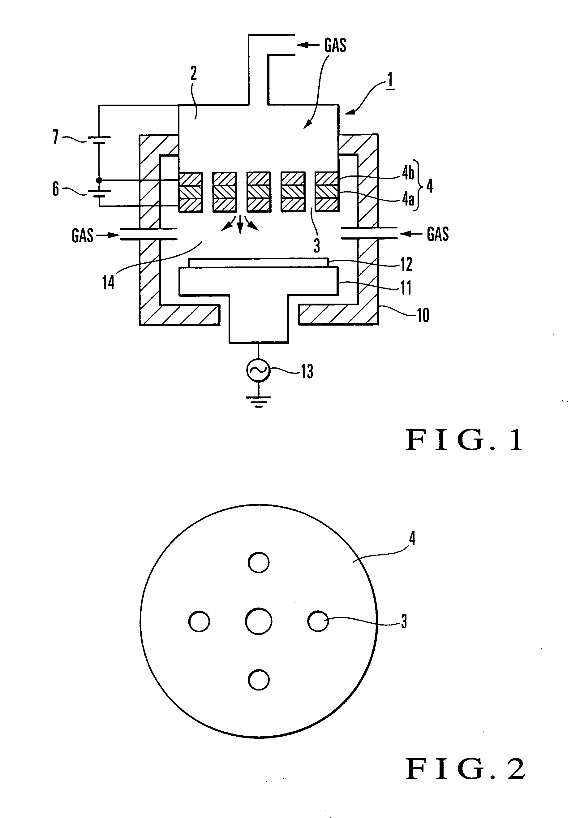
[0114] An example will be described in which the apparatus of the present invention is applied to pressurization of a gate electrode for the fabrication of a MOS transistor.
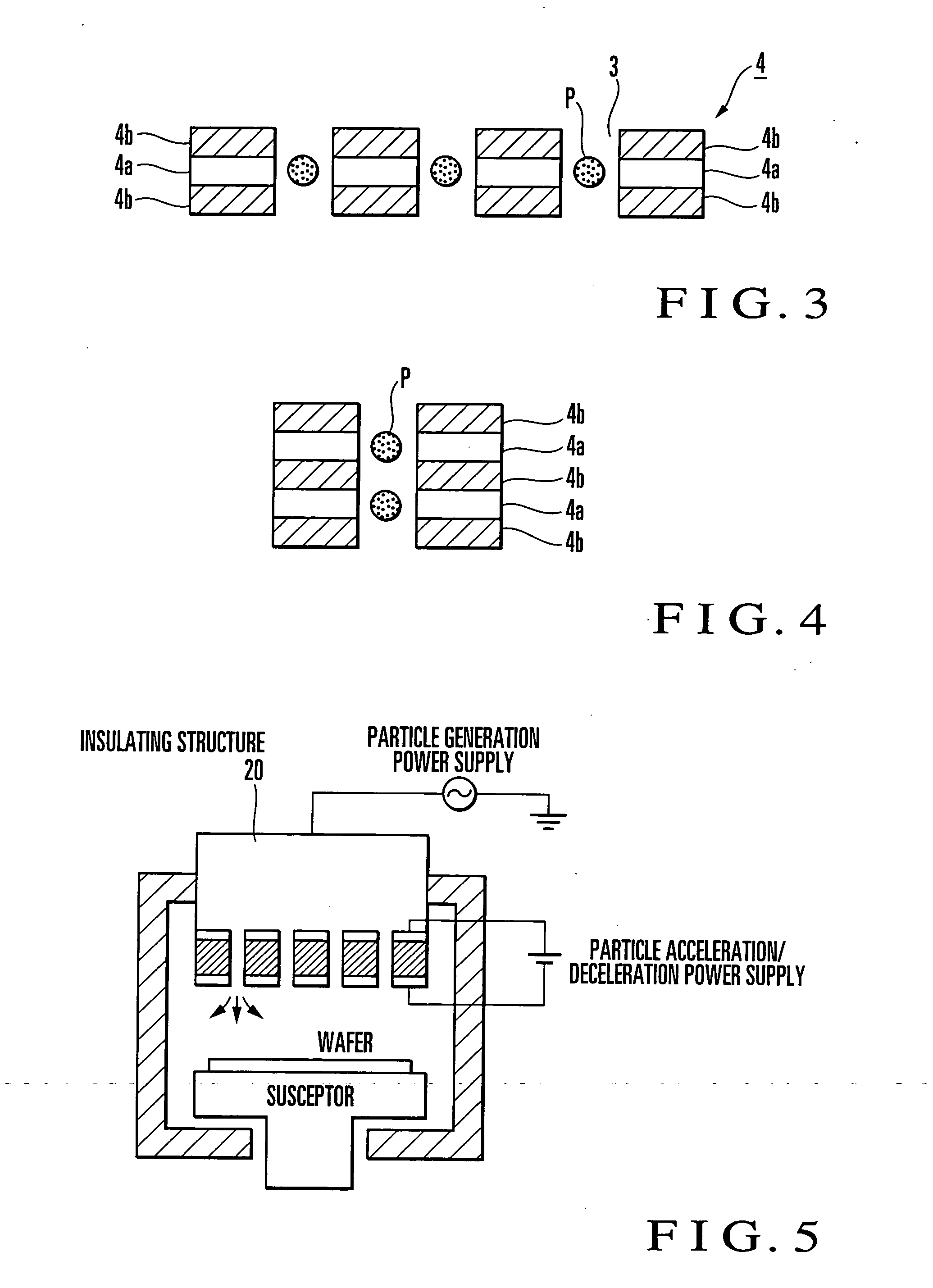
[0115] A poly-silicon film (thickness: 500 nm) formed on an underlying silicon oxide film (50 nm) is etched using a resist film (100 nm) as a mask. As the multielectrodes, 25 porous electrodes are fabricated each having a diameter of 100 μm and comprising a pair of a metal electrode and insulator.
[0116] He / Cl2 gas or Xe / Cl2 is introduced under the atmospheric pressure from the upper portion and is evacuated through the porous electrodes to maintain a reaction point pressure at 1 Torr. The sample described above is set 2.5 mm below the electrodes and is etched.
[0117] As the multielectrodes, five pairs of electrodes are set with respect to the lower extracting electrode, and a voltage was applied to the electrodes. A plasma is generated in the vicinity of the five pairs of cathode electrodes. As the ion species ...
example 2
[0121] The arrangement of this apparatus is basically the same as that of Example 1. As the gas (A), H2 / Xe gas is introduced under the atmospheric pressure from above the multielectrodes.
[0122] Evacuation is performed through the multielectrodes to maintain the pressure in the lower reaction chamber at about 10 Torr. SiH4 / H2 or SiH4 / Xe gas is introduced from the lower electrode to deposit a crystallite silicon thin film on the glass substrate. The substrate temperature is set to 300° C. The glass substrate is used as the sample the distance between the multielectrodes and the sample is about 10 mm.
[0123] In the multielectrodes, a large amount of H radicals are generated by the reaction of H2+e→H+H, Xe+e→Xe++e+e and introduced into the reaction chamber. The substrate is irradiated with high-speed H radicals with an energy of about 5 eV or less in the same manner as in Example 1.
[0124] A large amount of SiH3 radicals are generated by the reaction of H+ SiH4→SiH3+H2 to serve as a th...
example 3
[0127] The arrangement of this apparatus is basically the same as that of Example 2. High-frequency power of 400 MHz and that of 450 KHz are applied to the substrate electrode 2 (FIG. 23). As the gas (A), a gas such as Ar, O2, or N2 is introduced from the above the multielectrodes at the atmospheric pressure. C4F6, C4F8, or the like is introduced from the lower electrode to form on the Si substrate. SiO2, SiOCH, organic film SIC, SiCN, or the like is processed using a patterned resist or the like as a mask.
[0128] Ar+, O+, or N+ electrons, or O or N radicals are generated in the multielectrodes to inject various types of energy-controlled particles into the reaction chamber.
[0129] In the reaction chamber, a plasma has been generated by the 400-MHz high-frequency with the gas such as C4F8 or C4F6. Ions in the plasma are introduced into the substrate by the 450-KHz high frequency. Whether the 450-KHz high frequency is to be applied or not may be decided appropriately in accordance wi...
PUM
| Property | Measurement | Unit |
|---|---|---|
| Distance | aaaaa | aaaaa |
| Pressure | aaaaa | aaaaa |
| Electric potential / voltage | aaaaa | aaaaa |
Abstract
Description
Claims
Application Information