
Electron beam drift correction method and electron beam writing method

Active Publication Date: 2007-02-01
NUFLARE TECH INC
View PDF22 Cites 49 Cited by
  • Summary
  • Abstract
  • Description
  • Claims
  • Application Information

AI Technical Summary

Benefits of technology

[0010] An object of one currently preferred form of the present invention is to provide an electron beam drift correction method capable of avoiding the problems and further reducing in number beam drift correction processes while handling disturbances. An object of another form of the invention is to provide an electron beam writing method with an ability to suppress degradation of pattern depiction accuracy.

Problems solved by technology

This orbit change is called the “beam drift.” The beam drift is hardly predictable, so it is very difficult to provide an effective way of correcting the beam drift through estimation without measurement.
In view of this nature, if drift correction is simply performed at fixed time intervals having a length which is made equal to that in the initial period with the risk of appreciable beam drifts while forcing the pattern depiction to be interrupted on each occasion, then the number of drift correction operations increases accordingly, resulting in an increase in depiction time and thus a decrease in throughput.
However, beam drifts can also be occurred by other causes except the one stated above—i.e., due to the presence of disturbances.
These disturbances occur irregularly and unexpectedly at any time during pattern writing.
This poses another problem as to insufficiency of the drift correction number reducibility.
Additionally, beam deflectors can decrease in deflection sensitivity due to disturbances.
Unfortunately, prior art approaches fail to provide any successful technique for compensating such deflection sensitivity degradation.
In addition, while a Z-axis or “Z” sensor is used to detect a position in a Z-axis direction on the pattern depiction surface of a target workpiece, it will possibly happen that its optical axis is displaced or offset due to disturbances.
Prior art EB lithography systems fail to provide any effective remedy for such Z-sensor axis variations.

Method used


Image

  • Electron beam drift correction method and electron beam writing method
  • Electron beam drift correction method and electron beam writing method
  • Electron beam drift correction method and electron beam writing method

Examples


embodiment 1

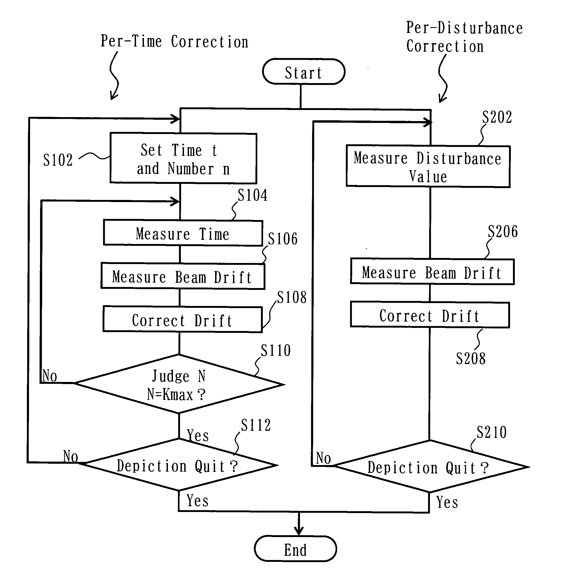
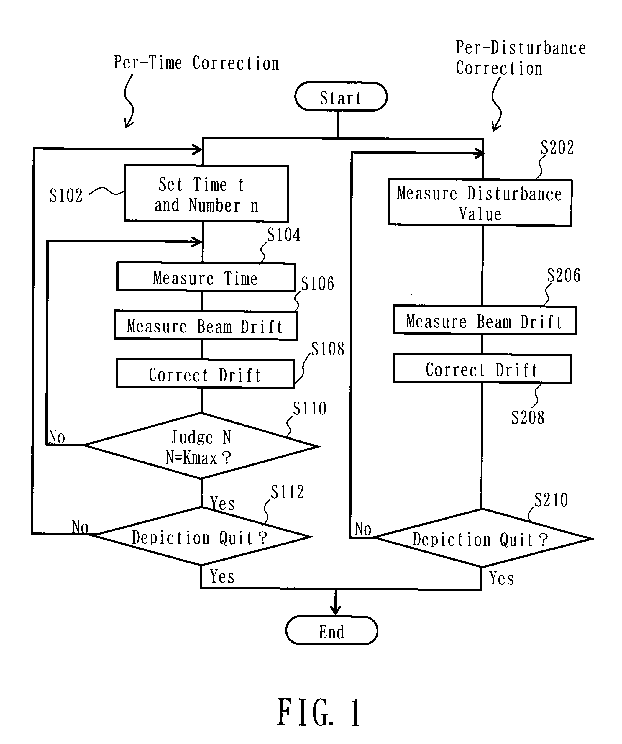
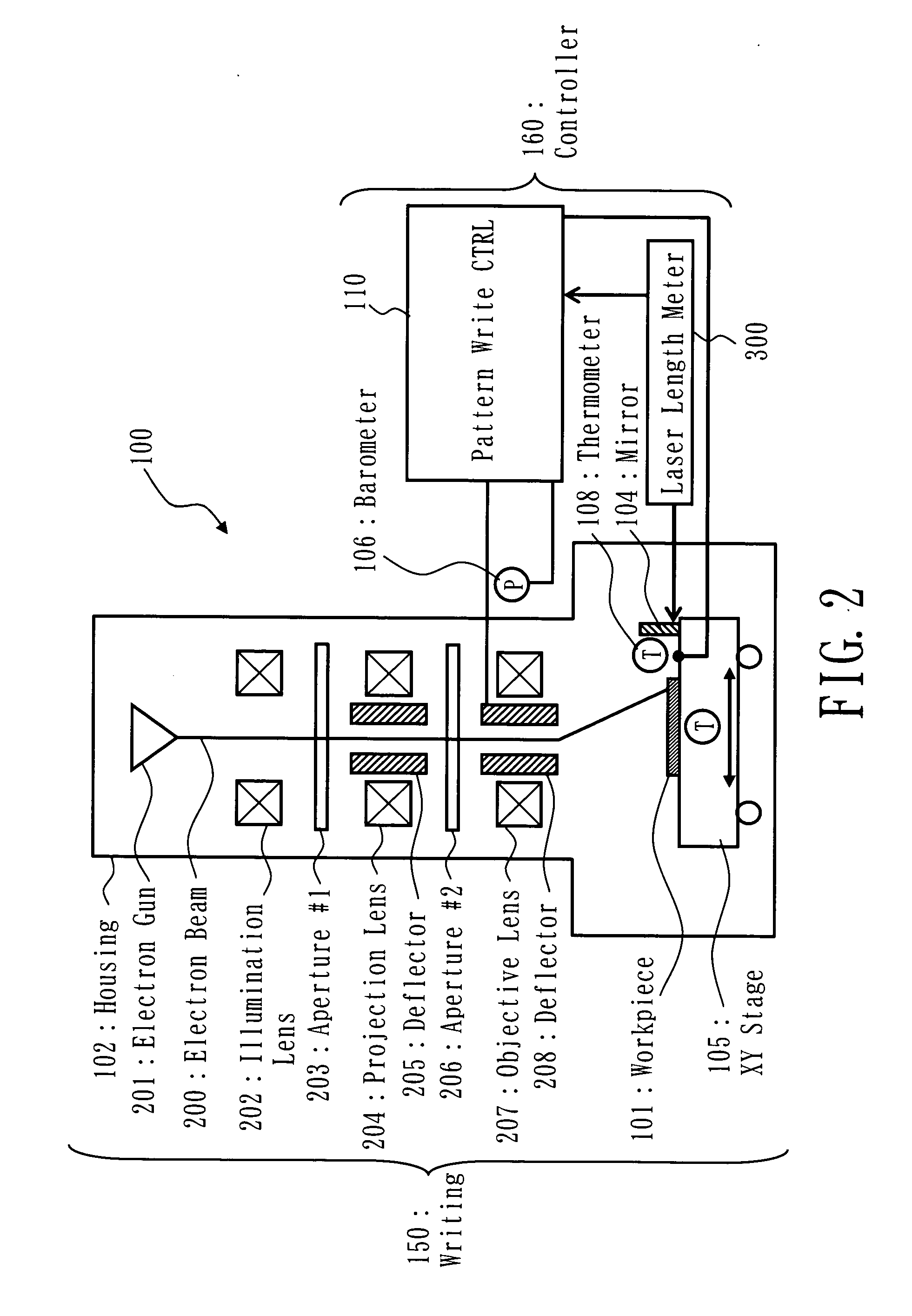
[0040] Referring to FIG. 1, main part of an electron beam drift correction method in accordance with a first embodiment of the invention is shown, which method is for use with an electron beam (EB) photolithography apparatus shown in FIG. 2. As shown in FIG. 1, the beam drift correction method includes a per-time correction process and a per-event correction process, wherein the former is for periodically performing electron beam drift correcting operations once per elapse of unit of time period while letting this unit time be variable in length whereas the latter is to perform electron beam drift correction, irrespective of the elapse of unit time, at any time when a change in value of certain kind of disturbance factor becomes equal to or greater than a prespecified level. The per-time or “regular” correction process performs a series of processes at steps which follow: a setup step S102 of setting up a correction time period “t” and a correction number “n”, a time period measurin...

embodiment 2

[0082] Turning to FIG. 13, an electron beam drift correction method also embodying the invention is shown in flowchart form, which method includes processes of correcting main and auxiliary deflection coefficients along with an offset of Z sensor.

[0083] This method performs electron beam drift correction in a similar way to that of the method of the previous embodiment shown in FIG. 1—that is, it performs the periodical per-time beam drift correction at length-variable time intervals and, in addition thereto, the per-disturbance drift correction to be performed at any time when a change in certain disturbance factor value becomes greater than or equal to a predetermined level. The periodical correction is done at steps S100 through S112 of FIG. 1, although these steps are not shown herein for purposes of convenience in the drawing. The per-disturbance correction is performed at steps S202 to S210 shown in FIG. 13, including pattern write interruption at step S204, beam drift measur...


PUM


Abstract

A method for correcting drifts of an electron beam, includes periodically correcting drift of the electron beam once per time period while varying the time period in length, and correcting, in addition to the correction per time period, the drift of the electron beam regardless of elapse of said time period when a change in value of a specified disturbance factor occurs with a prespecified change amount.

Description

CROSS-REFERENCE TO RELATED APPLICATION [0001] This application claims priority to Japanese Patent Application No. 2005-194930, filed Jul. 4, 2005 and Japanese Patent Application No. 2006-133873, filed May 12, 2006, the disclosure of which is incorporated herein by reference. FIELD OF THE INVENTION [0002] The present invention relates generally to energy radiation photolithography technologies and, more particularly, to methodology for using a charged particle beam, such as an electron beam, to form a pattern on a target workpiece. More particularly but not exclusively, the invention relates to beam drift correction techniques for use in electron beam pattern writing or “drawing” apparatus. RELATED ART OF THE INVENTION [0003] Microlithography techniques promise advances in miniaturization of semiconductor devices and are becoming more important in the formation of highly integrated on-chip circuit patterns among semiconductor fabrication processes. In recent years, as ultralarge-scal...

Claims


Application Information

Patent Timeline
IPC IPC(8): G01N23/00
CPCB82Y10/00H01J2237/31793H01J37/3174B82Y40/00G03F7/2059Y10S430/143
Inventor IIZUKA, OSAMUHATTORI, KIYOSHI
Owner NUFLARE TECH INC
Features
  • Generate Ideas
  • Intellectual Property
  • Life Sciences
  • Materials
  • Tech Scout
  • Unparalleled Data Quality
  • Higher Quality Content
  • 60% Fewer Hallucinations
Learn More