Optical pulse compressor and optical function generator, optical pulse compressing method and optical function generating method

a technology of optical function generator and compressor, applied in multiplex communication, optical elements, instruments, etc., can solve the problems of distorted waveform of pulse to be compressed, limited compression ratio, and inability to acquire large amount of chirp, etc., to achieve high-quality, convenient and fast operation, and high-quality

Inactive Publication Date: 2007-02-01
JAPAN SCI & TECH CORP
View PDF3 Cites 32 Cited by
  • Summary
  • Abstract
  • Description
  • Claims
  • Application Information

AI Technical Summary

Benefits of technology

[0034] The present invention enables efficient compression of a train of low-power, high-repetition-frequency pulses in the optical communication wavelength range and can implement a practical, economical, and high-quality short optical pulse source for ultra-high speed optical communication.

Problems solved by technology

The general low-power optical pulse used in ultra-high speed optical communication, however, cannot acquire large amount of chirp, and the compression ratio is limited.
A great compression ratio will require a great amount of dispersion to compensate for the chirp, but the third-order disp

Method used


Image

  • Optical pulse compressor and optical function generator, optical pulse compressing method and optical function generating method
  • Optical pulse compressor and optical function generator, optical pulse compressing method and optical function generating method
  • Optical pulse compressor and optical function generator, optical pulse compressing method and optical function generating method

Examples


first embodiment

A. First Embodiment

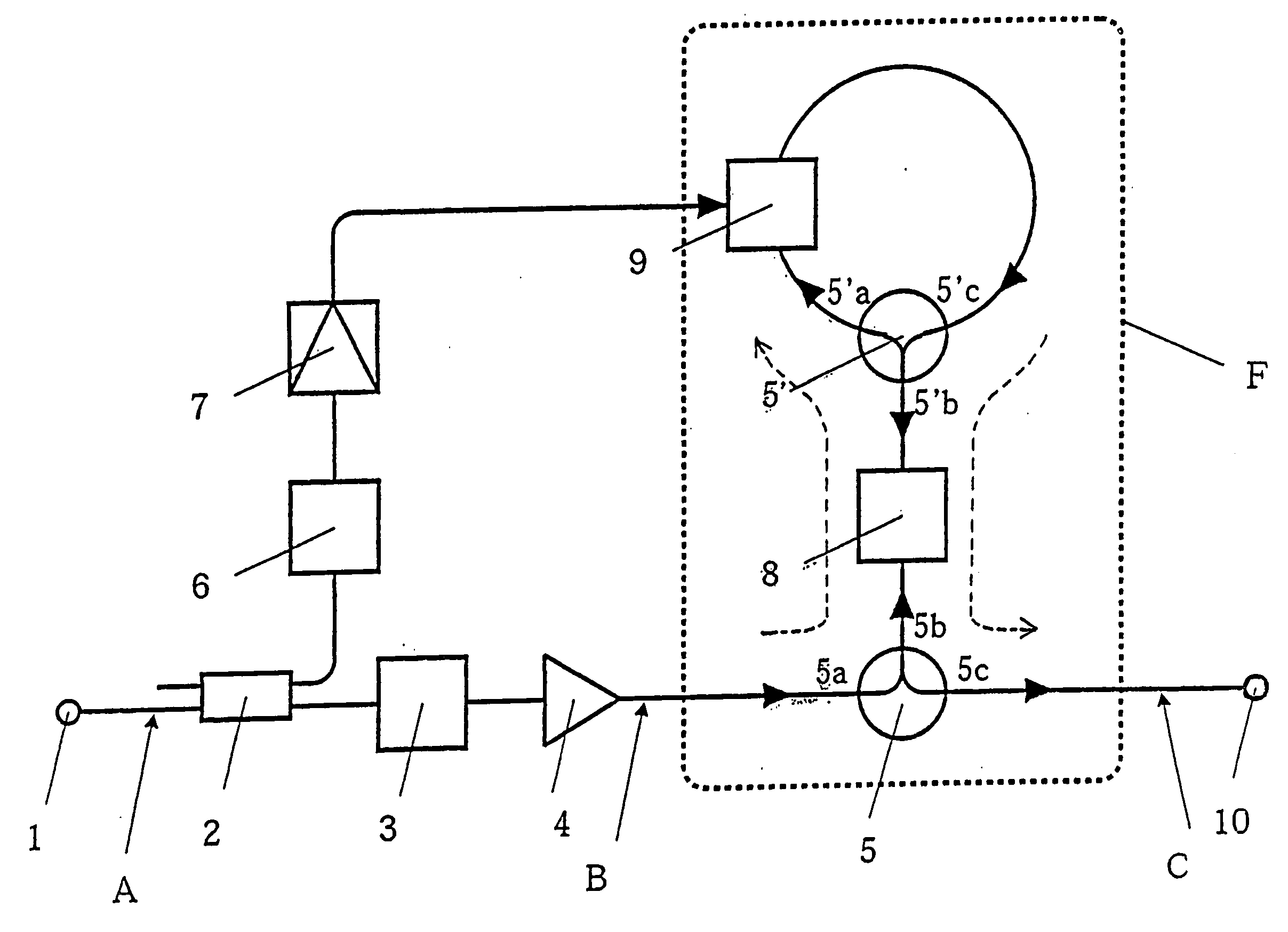
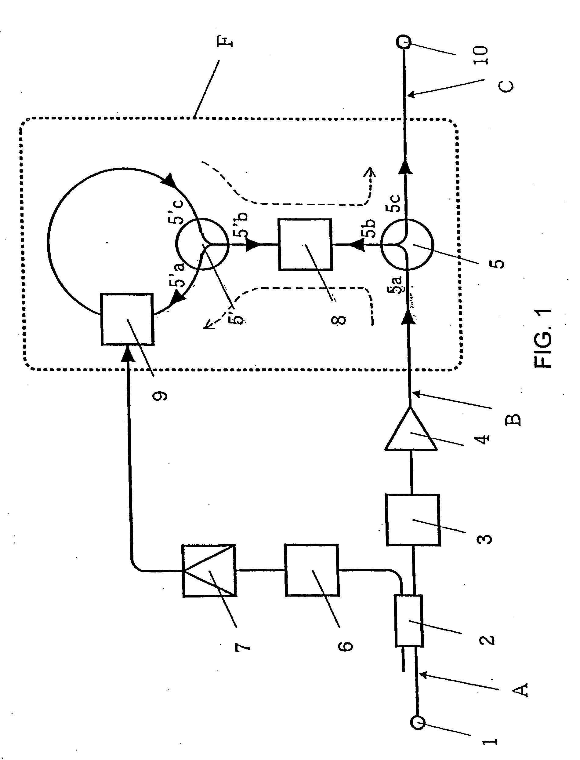
[0046]FIG. 1 is a view showing the configuration of an optical pulse compressor of a first embodiment. The optical compressor includes an optical input terminal 1, an optical coupler 2, an optical narrow-band filter 3, an optical amplifier 4, optical circulators 5 and 5′, a clock extraction circuit 6, an electric amplifier 7, a dispersive medium 8, an optical phase modulator 9, and an optical output terminal 10.

[0047] The optical input terminal 1 is connected through the optical coupler 2, the optical narrow-band filter 3, and the optical amplifier 4 to a port 5a of the optical circulator 5. The port 5a of the optical circulator 5 is connected through a port 5b, the dispersive medium 8, and a port 5′b of the optical circulator 5′ to a port 5′a. The ports 5′a and 5′c of the optical circulator 5′ are connected in a loop passing the optical phase modulator 9. The port 5b of the optical circulator 5 is connected through a port 5c to the optical output terminal 10. Th...

second embodiment

B. Second Embodiment

[0072]FIG. 8 is a view showing the configuration of an optical pulse compressor of a second embodiment. The configuration shown in FIG. 8 differs from the configuration shown in FIG. 1 in the following points: a dispersive medium 8 and an optical phase modulator 9 in an optical Fourier transform circuit F are interchanged, and an optical delay element 12 is placed after the dispersive medium 8 in a loop connecting ports 5′a and 5′c of an optical circulator 5′. The drive circuit of the optical phase modulator 9 receives a clock signal reproduced by a clock extraction circuit 6 and an electric amplifier 7 from an optical coupler 2, as in FIG. 1.

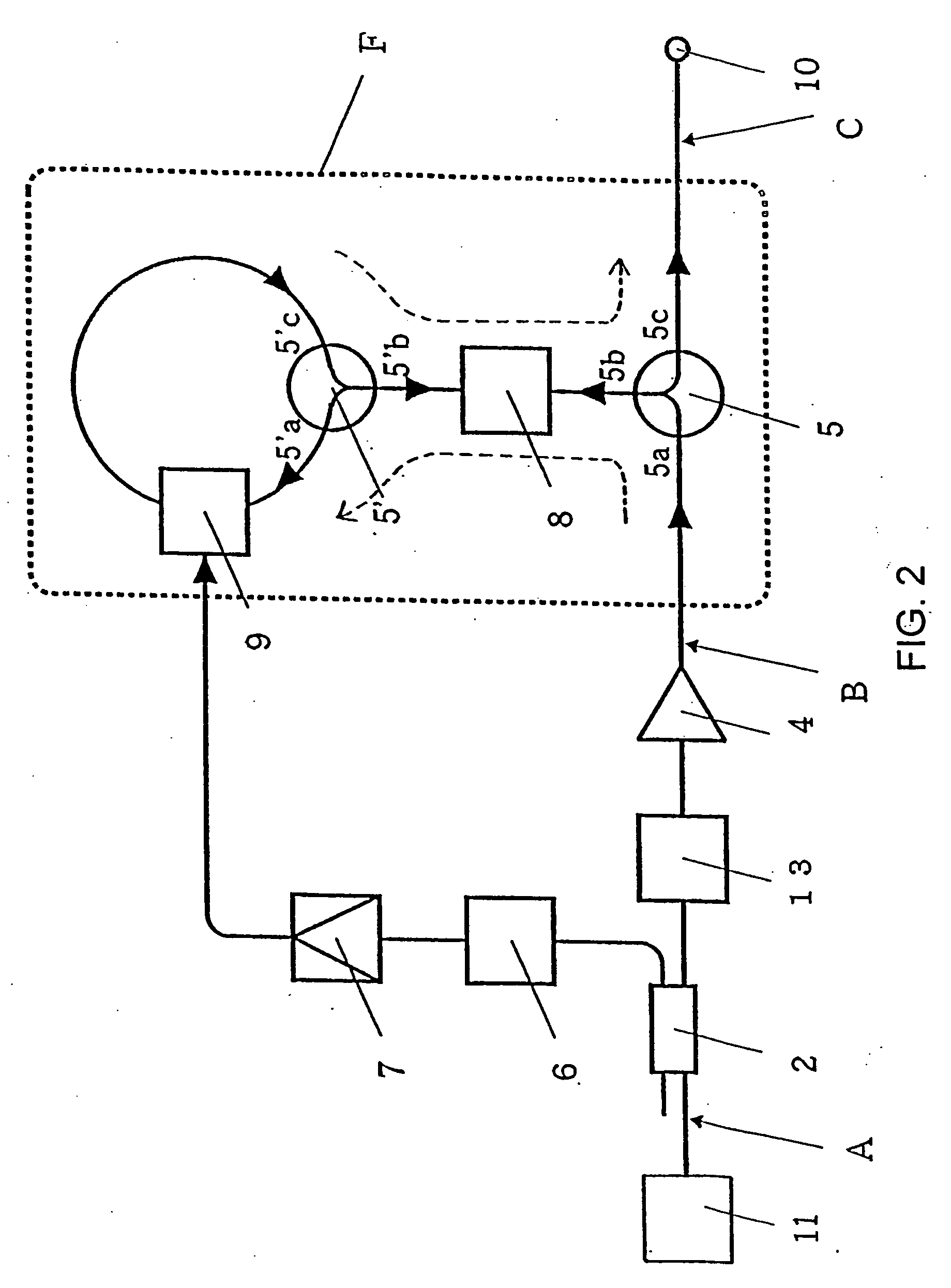
[0073]FIG. 9 is a view showing the configuration of an optical function generator of the second embodiment. The optical input terminal 1 of the optical pulse compressor of the second embodiment is replaced by an optical pulse generator 11, as in the first embodiment.

[0074] The operation of the optical pulse compressor and ...


PUM


Abstract

A small-sized, high-functionality optical pulse compressor capable of generating a low-power, high-repetition-frequency ultrashort pulse train used for ultralast optical communication and photometry, and a simple-structure optical function generator for realizing an arbitrary time waveform. The optical pulse compressor comprises and optical Fourier transform device (F) having an optical phase modulator (9) driven by the repetition-frequency of an input optical pulse train and a dispersive medium (8), for converting the shape of an input optical pulse frequency spectrum into its time waveform, and an optical filter (3) inserted ahead of the optical Fourier transform device (F), for reducing the spectrum width of an input optical pulse, wherein the optical Fourier transform device (F) converts a small-spectrum-width optical pulse output from the optical function generator generates an optical pulse. The optical function generator generates an optical pulse having an arbitrary time waveform by reproducing, as it is, a spectrum waveform-shaped arbitrarily by an optical filter on a time-axis by tch optical Fourier transform device (F).

Description

TECHNICAL FIELD [0001] The present invention relates to optical pulse compressors for compressing the time width of an optical pulse output from a optical pulse source at a desired rate and optical function generators for providing a desired pulse waveform, in the ultrashort pulse technology used for ultra-high speed optical communication and optical measurement. BACKGROUND ART [0002] General optical pulse compression technology can be broadly divided into a pulse compression technique using an optical fiber and a pair of diffraction gratings (first conventional technique) and a pulse compression technique based on soliton effect using a dispersion-decreasing fiber (second conventional technique). [0003] When a strong optical pulse is launched into a fiber, the first conventional technique converts the pulse into a broadband rectangular pulse having a linear chirp by normal dispersion and non-linearity (self-phase modulation effect) of the fiber. Then, the linearly chirped pulse is ...

Claims


Application Information

Patent Timeline
IPC IPC(8): H04B10/00G02F1/01G02F2/00G02F1/055H01S3/00H04J14/00
CPCG02F1/0553H04B10/508H01S3/0057G02F2203/26H04J14/00
Inventor NAKAZAWA, MASATAKAHIROOKA, TOSHIHIKO
Owner JAPAN SCI & TECH CORP
Why Eureka
Try Eureka