Acoustic wave sensor packaging for reduced hysteresis and creep

a technology of acoustic wave and sensor, applied in the field of sensing devices, can solve the problems of reducing the performance of the sensor, increasing the mass loading of the acoustic wave sensor, and the aqp structure, and achieve the effects of improving the performance of the acoustic wave sensing resonator, and reducing hysteresis and creep

Inactive Publication Date: 2007-02-08
HONEYWELL INT INC
View PDF19 Cites 19 Cited by
  • Summary
  • Abstract
  • Description
  • Claims
  • Application Information

AI Technical Summary

Benefits of technology

[0013] It is yet another aspect of the present invention to provide for a SAW torque sensor in which creep and hysteresis are reduced.
[0014] The aforementioned aspects and other objectives and advantages can now be achieved as described herein. An acoustic wave sensing apparatus and system is disclosed, which includes a substrate having a quartz surface. An acoustic wave sensing resonator is generally configured from the substrate, such that the quartz surface is attachable to a metal shaft utilizing an adhesive that reduces hysteresis and creep and improves the performance of the acoustic wave sensing resonator. The metal shaft is preferably polished in order to reduce the localized stress and contact area associated with the quartz surface of the acoustic wave sensing resonator and the metal shaft. The adhesive can be implemented as an epoxy adhesive that avoids direct-contact induced frequency instability associated with the contact area.
[0015] The acoustic wave sensing apparatus and/or system disclosed herein can incorporate the use of a substrate having a surface formed from a piezoelectric material. Such an acoustic wave sensing apparatus and/or system further utilizes an acoustic w

Problems solved by technology

Most acoustic wave chemical detection sensors, for example, rely on the mass sensitivity of the sensor in conjunction with a chemically selective coating that absorbs the vapors of interest resulting in an increased mass loading of the acoustic wave sensor.
The AQP structure, however, is quite expensive to manufacture.
Additionally, high temperature processes related to the AQP may reduce the sensor perfor

Method used


Image

  • Acoustic wave sensor packaging for reduced hysteresis and creep
  • Acoustic wave sensor packaging for reduced hysteresis and creep
  • Acoustic wave sensor packaging for reduced hysteresis and creep

Examples


Embodiment Construction

[0029] The particular values and configurations discussed in these non-limiting examples can be varied and are cited merely to illustrate at least one embodiment and are not intended to limit the scope thereof.

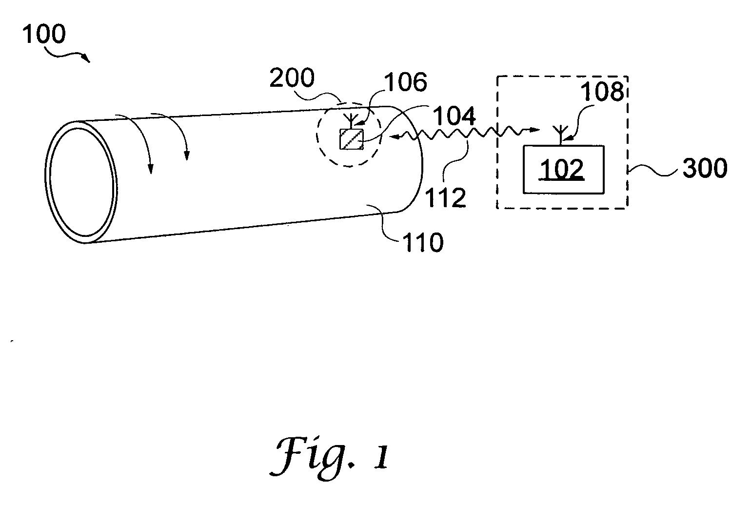
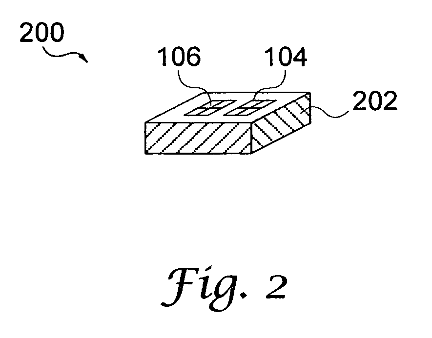
[0030]FIG. 1 illustrates a high-level diagram of a torque sensor system 100, which can be adapted for use in accordance with a preferred embodiment. Note that in FIGS. 1-6 herein, like or identical parts or elements are generally indicated by identical reference numerals. System 100 generally includes a rotating member 110 such as a shaft upon which a torque sensing element or sensor 104 can be located for detecting torque associated with rotating member 110. Torque sensor 104 incorporates an antenna 106, which can transmit and receive data to and from an electronics control unit 102 that incorporates an antenna 108. Note that the torque sensor 104 and its associated antenna 106 together can form a wireless torque sensor 200. The antenna 108 can be provided as, for example, a...


PUM


Abstract

An acoustic wave sensing apparatus includes a substrate having a polished piezoelectric surface. An acoustic wave sensing device (filter, resonator, or delay line) is generally configured from the substrate, such that the polished piezoelectric surface is attachable to a polished metal shaft utilizing an adhesive that reduces hysteresis and creep and improves the performance of the acoustic wave sensing device. The metal shaft is preferably polished in order to reduce the localized stress and contact area associated with the piezoelectric surface of the acoustic wave sensing device and the metal shaft. The adhesive can be implemented as an epoxy adhesive that avoids direct-contact induced frequency instability associated with the contact area.

Description

TECHNICAL FIELD [0001] Embodiments are generally related to sensing devices and components thereof. Embodiments also related to acoustic wave devices. Embodiments particular relate to surface acoustic wave (SAW) devices. Embodiments are additionally related torque sensors. BACKGROUND OF THE INVENTION [0002] Acoustic wave sensors are utilized in a variety of sensing applications, such as, for example, temperature and / or pressure sensing devices and systems. Acoustic wave devices have been in commercial use for over sixty years. Although the telecommunications industry is the largest user of acoustic wave devices, they are also used for in other areas for sensor applications, e.g., (chemical vapor detection). Acoustic wave sensors are so named because they use a mechanical, or acoustic, wave as the sensing mechanism. As the acoustic wave propagates through or on the surface of the material, any changes to the propagation path affect the characteristics of the wave. [0003] Changes in a...

Claims


Application Information

Patent Timeline
IPC IPC(8): G01N29/04
CPCG01N2291/02827G01L3/10G01L5/22H03H9/25H10N30/086
Inventor LIU, JAMES Z.T.
Owner HONEYWELL INT INC
Why Eureka
Try Eureka