Phase shift mask blank, photo mask blank, and manufacturing apparatus and method of blanks

Inactive Publication Date: 2007-02-15
HOYA CORP
View PDF16 Cites 0 Cited by
  • Summary
  • Abstract
  • Description
  • Claims
  • Application Information

AI Technical Summary

Benefits of technology

[0015] The present invention has been developed under the aforementioned background, and a first object thereof is to provide a phase shift mask blank in which the number of particles or pinholes each having a diameter larger than a diameter substantially equivalent in size to an exposure wavelength is reduced as much as possible.
[0016] Moreover, a second object of the present invention is to provide a manufacturing apparatus and method able to manufacture the phase shift mask blank in which the number of particles or pinholes each having the diameter larger than the diameter equivalent in size to the exposure wavelength is reduced as much as possible.
[0017] Furthermore, a third object of the present invention is to provide a photo mask blank in which the number of particles or pinholes is reduced as much as possible.

Problems solved by technology

These phase shift masks have a complicated constitution and require a high degree of manufacturing technique as compared with the conventional photo mask which has only the light strength information.
On the other hand, influences of a particle adhering to the mask blank and a pinhole formed in the mask have been increasingly regarded as problems.
Therefore, the blanks cannot be applied to some of photo mask blanks for KrF, in which a pattern finer than a conventional pattern is formed, or mask blanks for a short wavelength of ArF or F2 excimer laser.

Method used


Image

  • Phase shift mask blank, photo mask blank, and manufacturing apparatus and method of blanks
  • Phase shift mask blank, photo mask blank, and manufacturing apparatus and method of blanks
  • Phase shift mask blank, photo mask blank, and manufacturing apparatus and method of blanks

Examples


Embodiment Construction

.

[0078] Examples of the present invention will be described hereinafter in further detail.

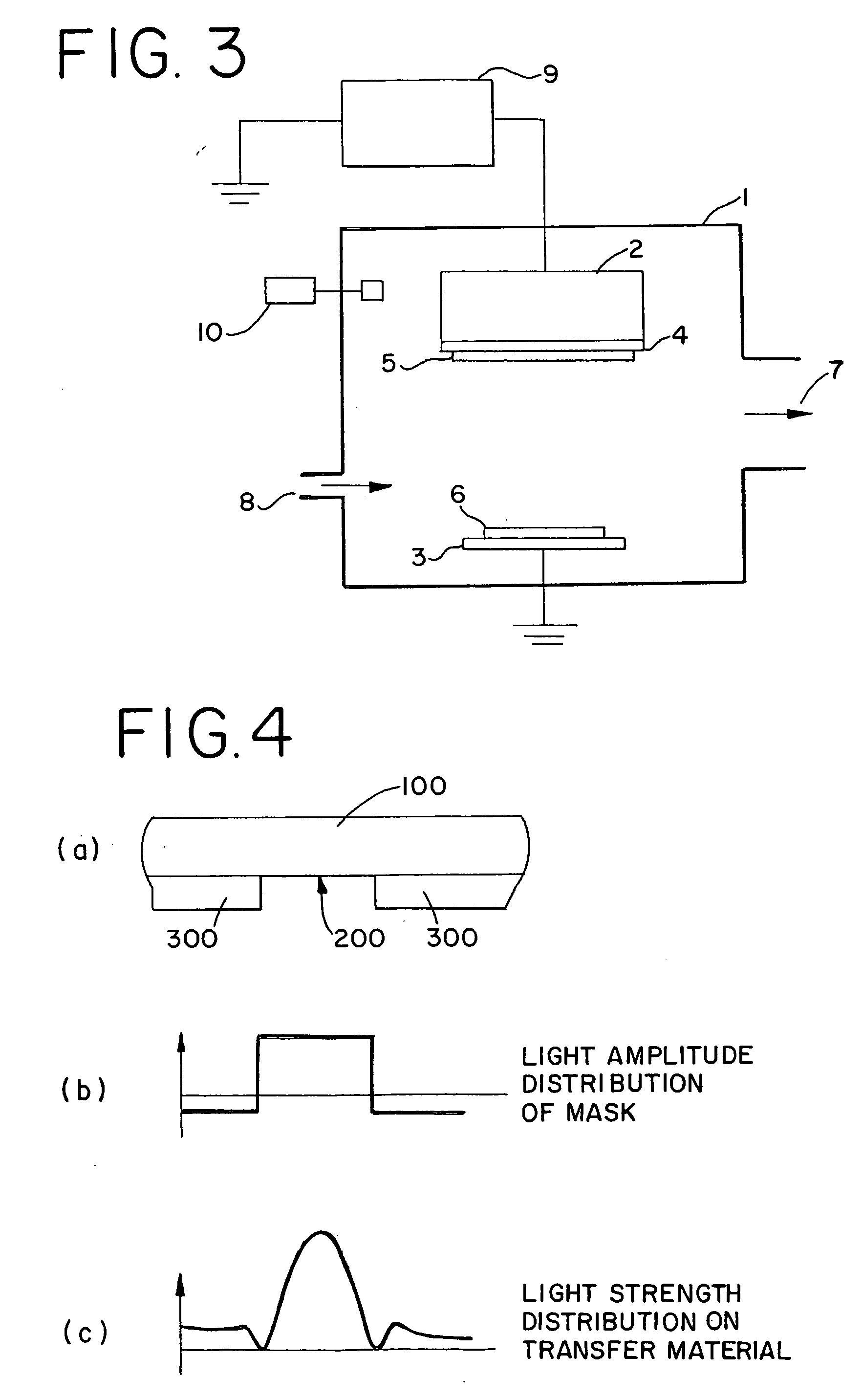
[0079] A DC magnetron sputtering apparatus shown in FIG. 3 was used, a combination of particle countermeasures shown in Table 1 is changed as shown in Table 2, and halftone phase shift mask blanks for ArF excimer laser (193 nm) were prepared.

[0080] Concretely, a mixed target (Mo:Si=8:92 mol %) of. molybdenum (Mo) and silicon (Si) was used to form a nitrided thin film (film thickness of about 670 angstroms) of molybdenum and silicon (MoSiN) on a transparent substrate by reactive sputtering (DC sputtering) in a mixed gas atmosphere (Ar:N2=10%:90%, pressure: 0.1 Pa) of argon (Ar) and nitrogen (N2). In this manner, the phase shift mask blank (film composition: Mo:Si:N=7:45:48) for ArF excimer laser (wavelength of 193 nm) was obtained.

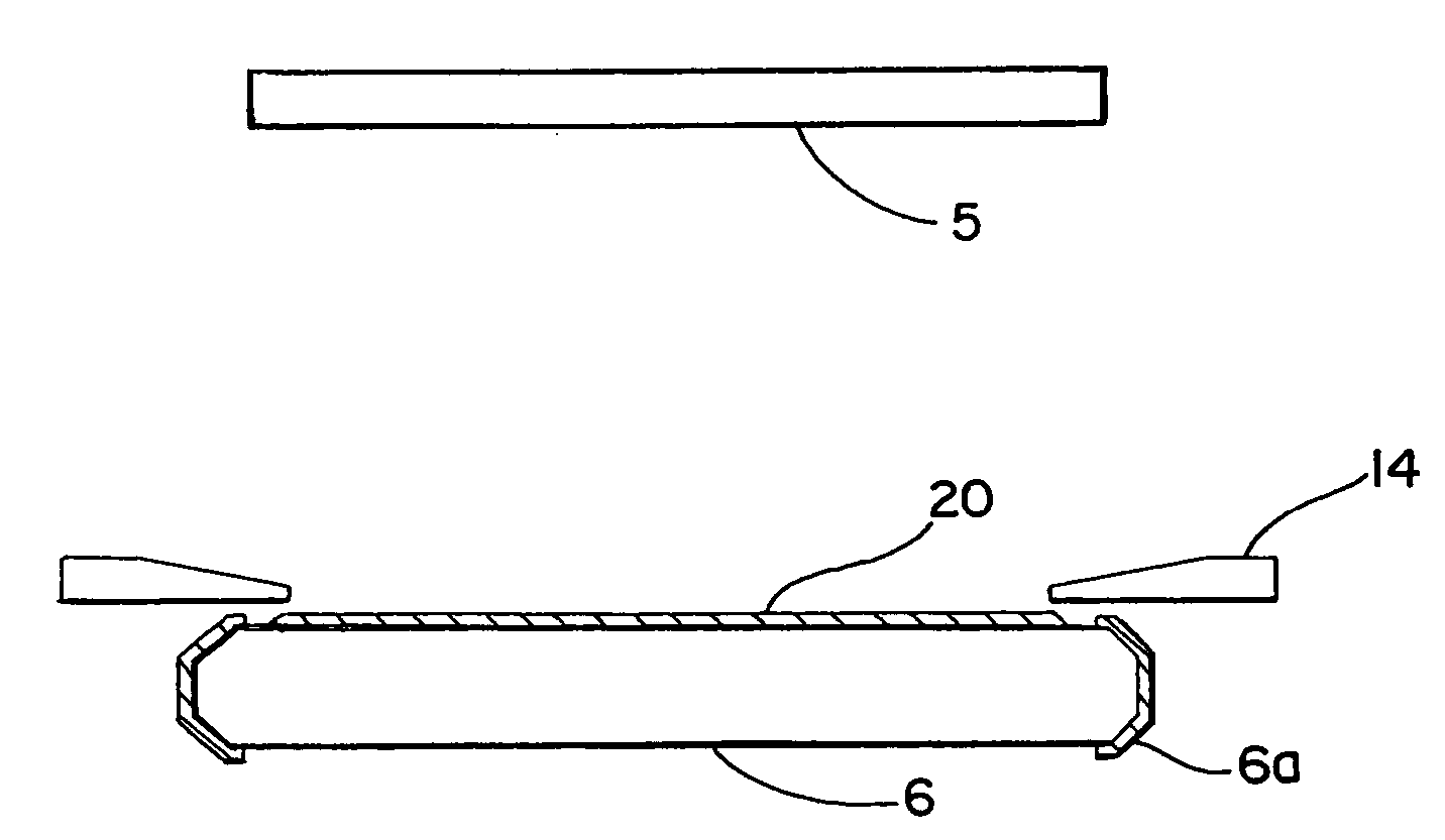
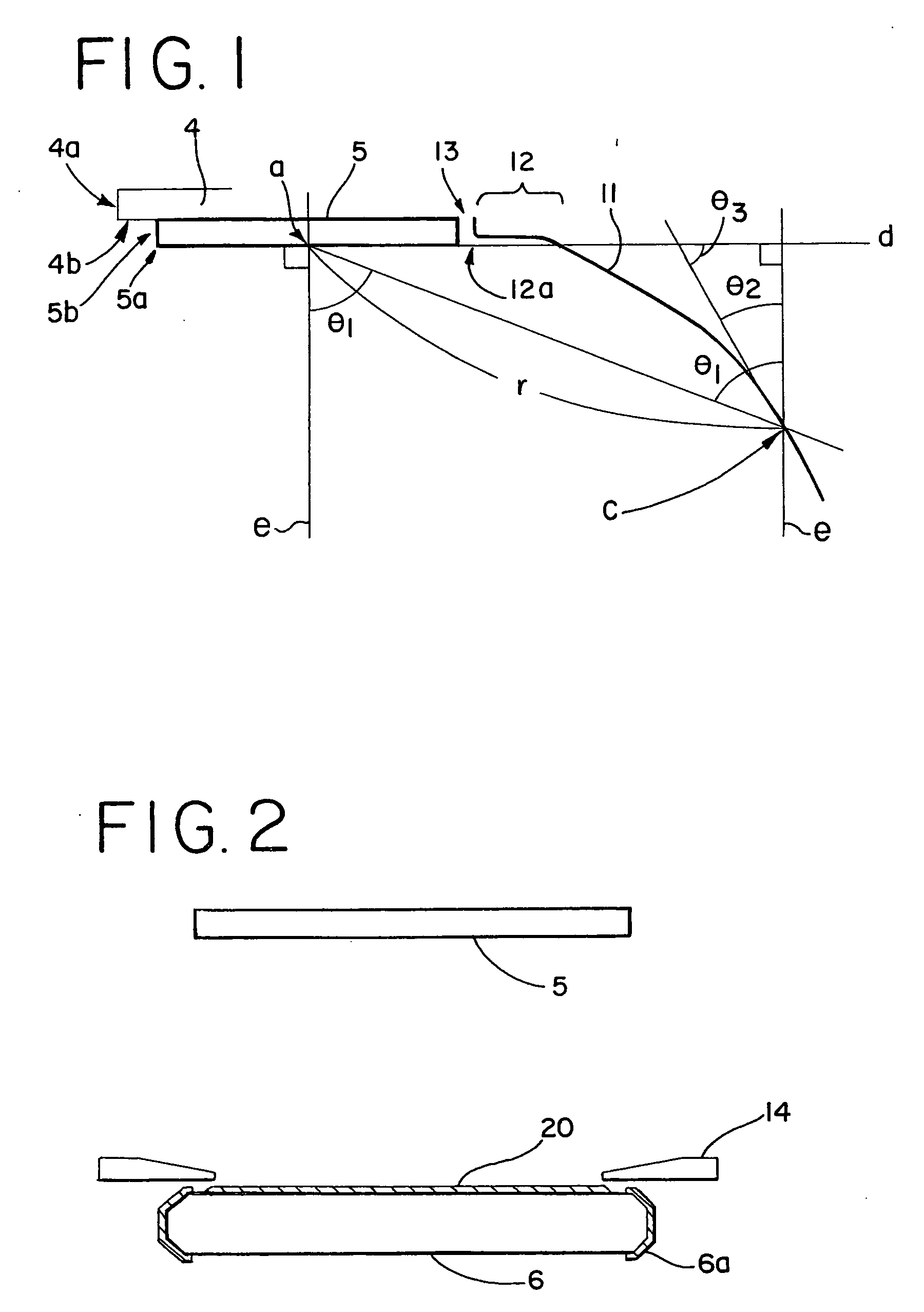
[0081] Here, the DC magnetron sputtering apparatus shown in FIG. 3 has a vacuum tank 1. A magnetron cathode 2 and substrate holder 3 are disposed in the vacuum tank...


PUM

PropertyMeasurementUnit
Diameteraaaaaaaaaa
Diameteraaaaaaaaaa
Temperatureaaaaaaaaaa

Abstract

There is provided a manufacturing apparatus and method able to manufacture a phase shift mask blank in which a total number of particles and pinholes having a diameter larger than about a half of an exposure wavelength in a light semi-transmission film is 0.1 or less per square centimeter. In a DC magnetron sputtering apparatus for manufacturing a halftone phase shift mask blank, for example, a target plane is disposed downwards with respect to a gravity direction, a whole-surface erosion cathode is used, a corner portion 5a of an end of a target and a corner portion of an earth shield are chamfered (R processed), a target end 5b, an exposed backing plate surface 4b and the surface of an earth shield 12 are roughened, and the earth shield 12 is disposed above a target plane d (on a backing plate side).

Description

[0001] This application claims the Paris convention priority of Japanese patent application 2000-277260 filed on Sep. 12, 2000, the entire disclosure of which is incorporated herein by reference. BACKGROUND OF THE INVENTION [0002] i) Field of the Invention [0003] The present invention relates to a phase shift mask blank which is suitable particularly for ArF or F2 excimer laser, and a manufacturing apparatus and method of the phase shift mask blank. [0004] ii) Description of the Related Art [0005] In recent years, it has been clarified that high resolution and focus depth are two important properties required for photolithography but are in a contradictory relation with each other, and that a practical resolution cannot be enhanced only by high NA and short wavelength of a lens of an exposure apparatus (Monthly Semiconductor World 1990.12, Applied Physics Vol. 60, November, 1991, and the like). [0006] Under such situation, phase shift lithography has been noted as the next-generatio...

Claims


Application Information

Patent Timeline
IPC IPC(8): C23C14/32C23C14/34C23C14/56G03F1/00G03F1/26G03F1/32G03F1/50G03F1/68G03F7/20H01L21/027
CPCC23C14/34C23C14/3414C23C14/35C23C14/564H01J37/3405G03F1/26G03F1/32G03F1/50G03F1/68G03F1/08
Inventor NOZAWA, OSAMUMITSUI, MASARUOOTSUKA, HITOSHIMITSUI, HIDEAKI
Owner HOYA CORP
Why Eureka
Try Eureka