Method for low NOx combustion of syngas/high hydrogen fuels

a high hydrogen content, syngas technology, applied in the direction of combustion using lump and pulverulent fuel, combustion type, combustion using catalytic material, etc., can solve the problems of polluting the air, inefficiency of conventional coal-fired steam plants, and inefficient sources of electrical power, so as to reduce the effect of s

a high hydrogen content, syngas technology, applied in the direction of combustion using lump and pulverulent fuel, combustion type, combustion using catalytic material, etc., can solve the problems of polluting the air, inefficiency of conventional coal-fired steam plants, and inefficient sources of electrical power, so as to reduce the effect of s

US20070037105A1Inactive Publication Date: 2007-02-15PRECISION COMBUSTION

Image

  • Method for low NOx combustion of syngas/high hydrogen fuels
  • Method for low NOx combustion of syngas/high hydrogen fuels
  • Method for low NOx combustion of syngas/high hydrogen fuels

Examples


Embodiment Construction

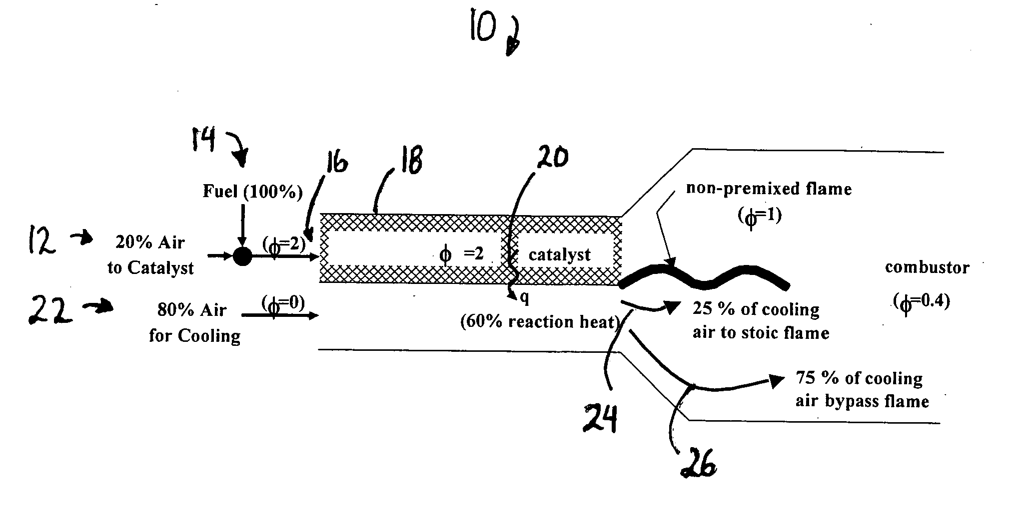
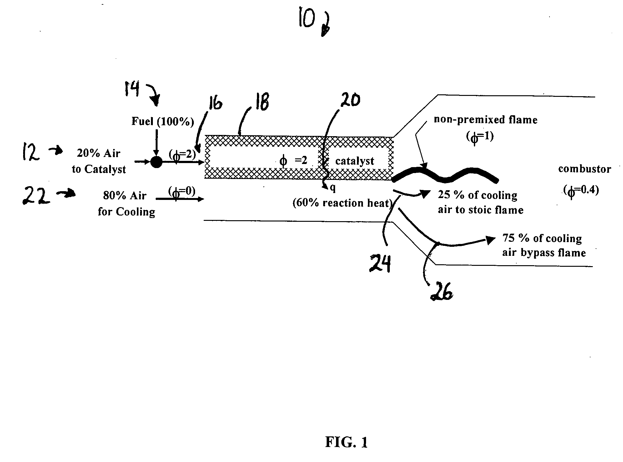
[0015] As shown for the example combustor 10 in FIG. 1, a twenty percent split of the combustion air 12 is mixed with the fuel 14 to form a fuel rich mixture 16 having an equivalence ratio of two, where a ratio of one is stoichiometric. Thus, a second twenty percent of the air is required to complete combustion. Complete conversion of the oxygen is assumed in a catalytic reactor 18 with sixty percent of the heat of combustion 20 (q) transferred to the balance of the combustion air 22. On contact of the reacted fuel with the remaining combustion air, only a second twenty percent of air 24 is required for stoichiometric combustion with the balance of the combustion air 22 bypassing the flame front. Thus, forty-five percent 26 of the reaction heat bypasses the flame zone reducing the heat liberated in the flame by about twenty percent.

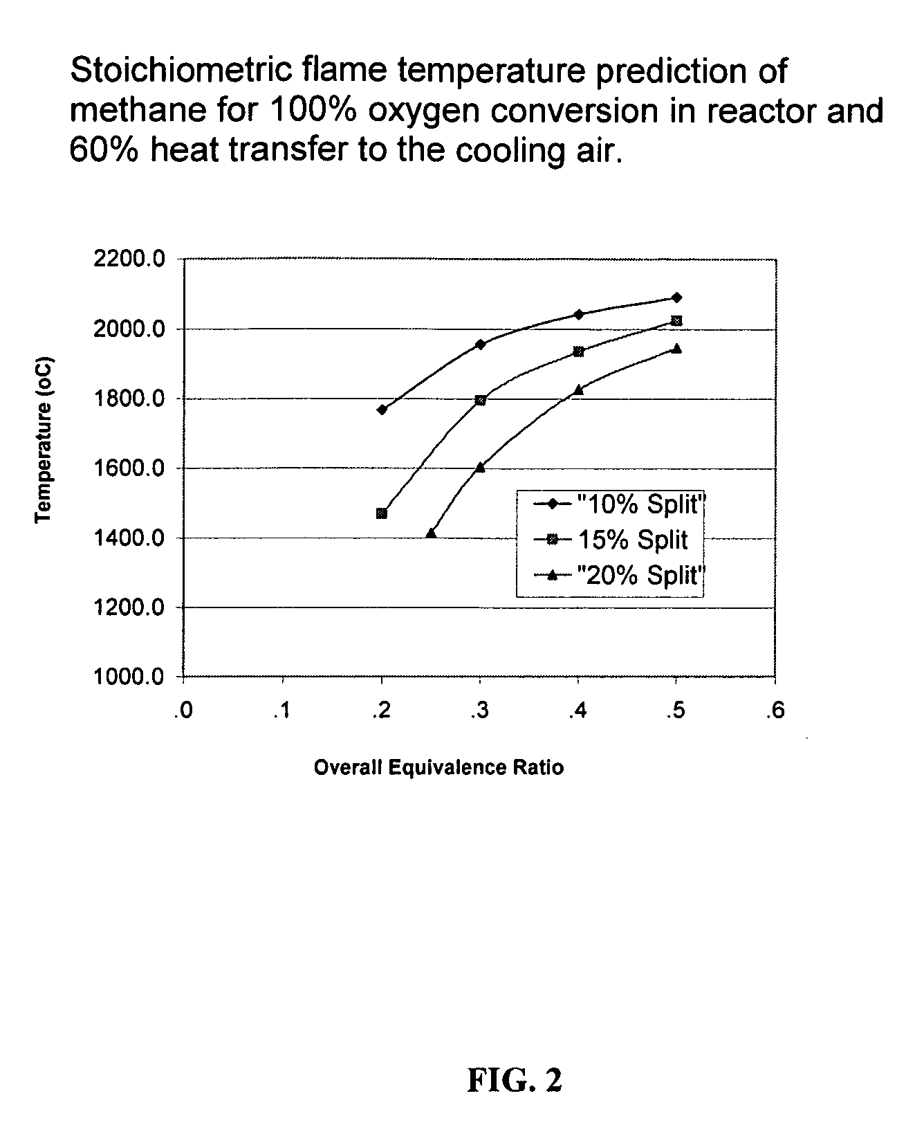
[0016] For conventional hydrocarbon fuels, including methane, the reduction in the heat liberated in the flame is not near enough for low NOx production...


PUM


Abstract

The present invention provides a method for low NOx combustion of high hydrogen content fuels in gas turbines. In the method of the present invention, at least a portion of the fuel is combusted under fuel rich conditions and a portion of resulting reaction heat is transferred to combustion air prior to non-premixed combustion of the fuel.

Description

CROSS-REFERENCE [0001] This application claims the benefit of U.S. Provisional Application No. 60 / 683,719 filed May 23, 2005.FIELD OF THE INVENTION [0002] The present invention relates to a method for ultra-low NOx combustion of high hydrogen content fuels. In one embodiment, the present invention provides a method for lowering the adiabatic flame temperature of a fuel prior to non-premixed combustion. BACKGROUND OF THE INVENTION [0003] With energy usage directly related to economic growth, there has been a steady increase in the need for increased energy supplies. In the U.S., coal is abundant and comparatively low in cost. Unfortunately, conventional coal-fired steam plants, which are a major source of electrical power, are inefficient and pollute the air. Thus, there is a pressing need for cleaner, more efficient coal-fired power plants. Accordingly, Integrated Gasification Combined Cycle (“IGCC”) coal technology systems have been developed which can achieve significantly improve...

Claims


Application Information

Patent Timeline
15 Feb 2007
Publication
US20070037105A1
IPC
F23D3/40; F23C5/00; F23M3/04; F23M3/02
CPC
F23C13/00; F23C2900/13002; F23R3/40; F23L15/04; F23C2900/9901; Y02E20/34
Inventors
PFEFFERLE, WILLIAM C.; KARIM, HASAN