Yttria sintered body, electrostatic chuck, and manufacturing method of yttria sintered body

a technology of electrostatic chuck and yttria sintered body, which is applied in the direction of manufacturing tools, mechanical equipment, natural mineral layered products, etc., can solve the problems of affecting the quality of yttria sintered body, etc., to achieve uniform distribution of chucking forces, improve bonding strength, and excellent mechanical strength

Active Publication Date: 2007-02-22
NGK INSULATORS LTD
View PDF5 Cites 25 Cited by
  • Summary
  • Abstract
  • Description
  • Claims
  • Application Information

AI Technical Summary

Benefits of technology

[0021] The base body may preferably be made by a yttria sintered body, which contains an amount of silicon carbide within a range of 10 to 30% by volume. This allows the base body and the dielectric layer to have a diminished difference between their coefficients of thermal expansion, allowing for a improved bonding strength therebetween. In addition, by successful prevention of occurrences of a warp of the dielectric layer due to the sintering or such, the dielectric layer is allowed to have a maintained evenness in thickness, allowing for a uniform distribution of chucking forces. Further, the combination of base body and dielectric layer both made by a yttria sintered body having an excellent mechanical strength and corrosion resistance allows for provision of an electrostatic chuck with a very high mechanical strength and corrosion resistance.
[0022] The electrostatic chuck may preferably further comprise a terminal configured to connect the electrode to a power supply member; and a connecting member buried in the base body, joined to the electrode and the terminal, and configured to interconnect the electrode and the terminal. This allows that part of the base body which tends to have a reduced strength such as by provision of a hole for insertion of the terminal, to be reinforced by burial of the connecting member, allowing for an enhanced mechanical strength of the electrostatic chuck.
[0023] The connecting member may preferably have a joint face with the electrode and a joint face with the terminal at a distance of 1 mm or more from each other. This allows the electrostatic chuck to be reinforced more adequately, allowing for a yet enhanced mechanical strength thereof.
[0024] The connecting member may preferably contain at least one of platinum and niobium. This allows the base body and the connecting member to have their coefficients of thermal expansion come close to each other, allowing for successful prevention of occurrences of cracks due to burial of the connecting member in the base body.
[0025] According to an aspect of the invention, a manufacturing method of a yttria sintered body comprises preparing raw material powder containing an amount of silicon carbide within a range of 5 to 40% by volume, and yttria, forming a compact using the raw material powder, and sintering the compact in an inert gas atmosphere within a temperature range of 1500 to 2000° C. According to this aspect, the manufacturing method is allowed, by inclusion of silicon carbide within the range of 5 to 40% by volume, to provide a yttria sintered body having an excellent mechanical strength and corrosion resistance, while having a controlled volume resistivity.
[0026] The sintering may preferably comprise sintering the compact by a hot pressing method. This allows for a more densified yttria sintered body having an enhanced mechanical strength and corrosion resistance.

Problems solved by technology

Then, a trial was made of application of a highly corrosion-resistant yttria sintered body to an electrostatic chuck, with an encountered new problem.
The yttria sintered body is inferior in some mechanical properties, such as flexural strength and fracture toughness.
As the yttria sintered body constitutes the electrostatic chuck, inferiority in some mechanical properties may cause damages in processes of the manufacturing, with a reduced yield.
For example, cracks or chipping may occur when drilling a hole for insertion of a terminal to be joined to an electrode, or cracks may develop with thermal stresses when brazing a terminal to an electrode.
However, the volume resistivity of conventional yttria sintered bodies reside in an unfavorable range for the electrostatic chuck to be adapted to make use a Johnsen-Lahbek force, thus failing to provide a high chucking performance.

Method used


Image

  • Yttria sintered body, electrostatic chuck, and manufacturing method of yttria sintered body
  • Yttria sintered body, electrostatic chuck, and manufacturing method of yttria sintered body
  • Yttria sintered body, electrostatic chuck, and manufacturing method of yttria sintered body

Examples


examples

[0112] There will be detailed examples of the embodiments, while the invention is not limited thereto.

Examples of Yttria Sintered Body

[0113] Embodiment examples 1 to 4 and comparative examples 1 and 2

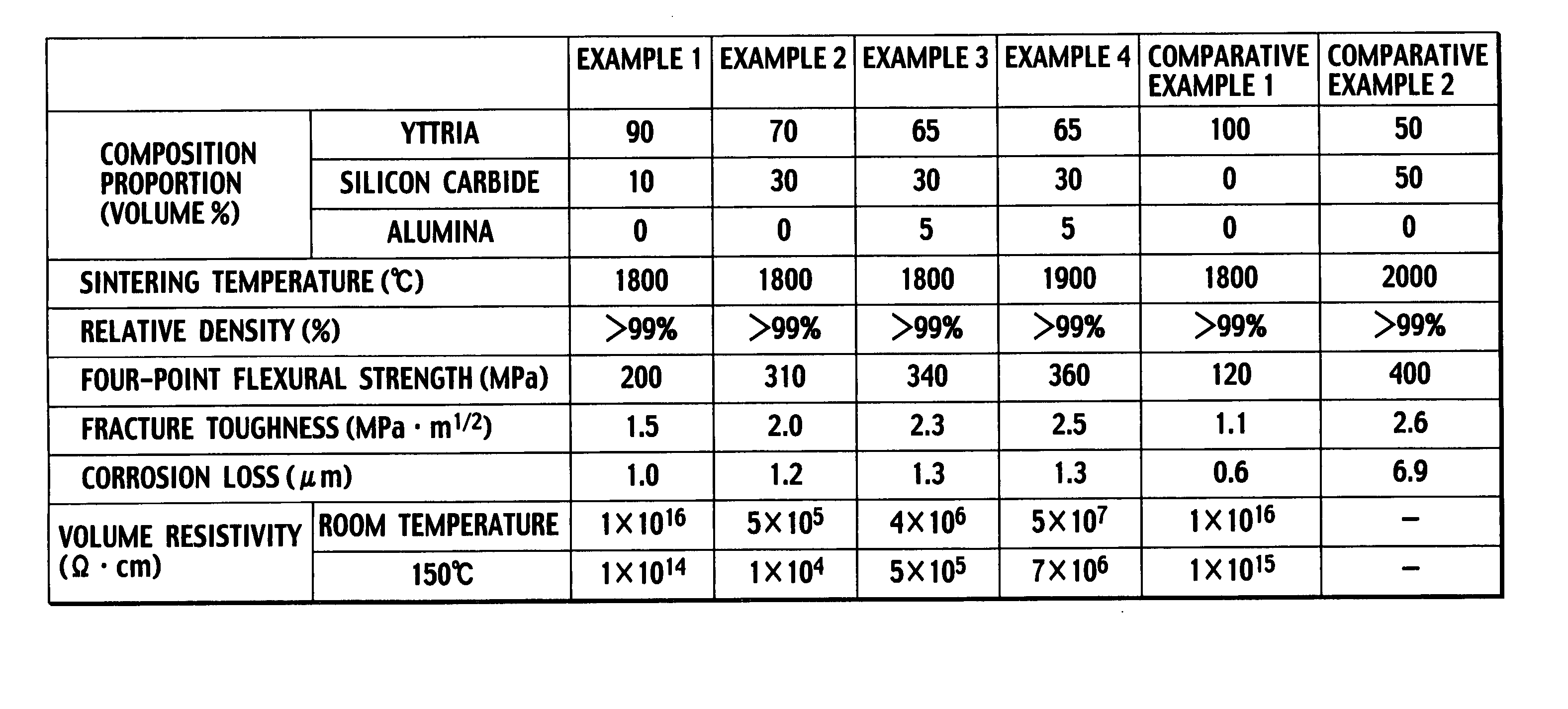
[0114] Description is now collectively made of embodiment examples 1 to 4 and comparative examples 1 and 2.

[0115] Embodiment examples 1 and 2, as well as comparative example 2, are examples of a yttria sintered body composed of yttria and silicon carbide, where powder of yttria and powder of silicon carbide were weighed and mixed for preparation of raw material powder, so that yttria and silicon carbide had their composition ratios shown in Table 1.

[0116] Embodiment examples 3 and 4 are examples of a yttria sintered body containing alumina, besides yttria and silicon carbide, where powder of yttria, powder of silicon carbide, and powder of alumina were weighed and mixed for preparation of raw material powder, so that yttria, silicon carbide, and alumina had their composition ratios...

embodiment example 5

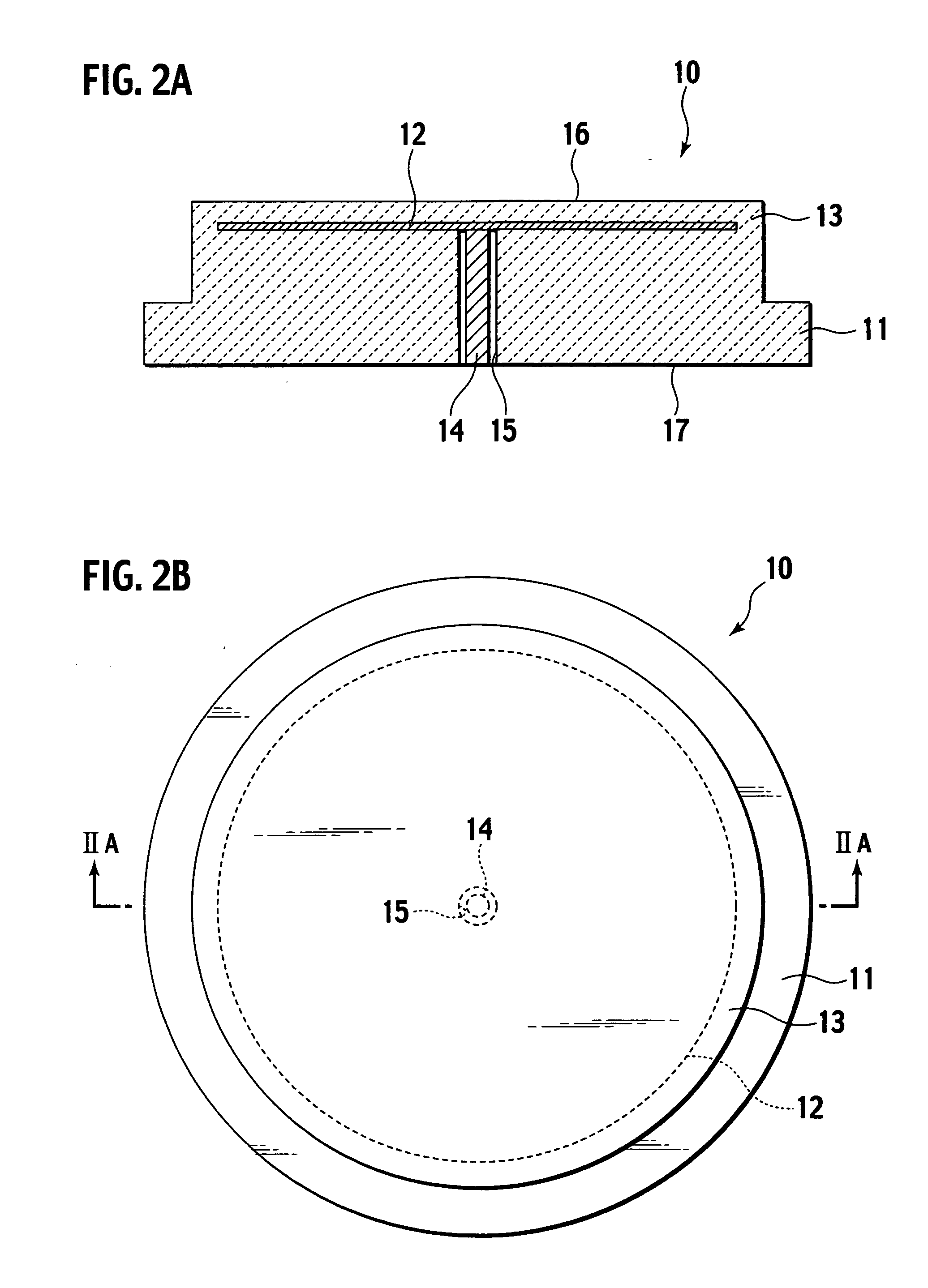
[0131] There was manufactured an electrostatic chuck 10 of FIGS. 2A and 2B having a base body 11 made by a yttria sintered body.

[0132] First, yttria powder of an average particle size of 1 μm and silicon carbide powder of an average particle size of 0.5 μm were mixed, by composition ratios of 70% by volume of yttria and 30% by volume of silicon carbide, to prepare raw material powder. To the raw material powder, water, a dispersing agent, and polyvinyl alcohol (PVA) as a binder were added, and mixed together by a trommel to prepare a slurry. This slurry was atomized and dried by a spray dryer for preparation of granulated granules.

[0133] Granulated granules were filled in a molding die, where they were pressed in the direction of a single axis to form a compact. The compact was packed in a carbon sheath, and sintered by a hot pressing method in a nitrogen atmosphere at a sintering temperature of 1,900° C., to form a base body 11 of yttria sintered body.

[0134] Next, a print paste ...

embodiment example 6

[0139] There was manufactured an electrostatic chuck 30 of FIGS. 4A and 4B having a base body 31 made by an alumina sintered body.

[0140] Granulated granules prepared like the embodiment example 5 were filled in a molding die, where they were pressed in the direction of a single axis to form a compact. This compact was packed in a carbon sheath, and sintered by a hot pressing method in a nitrogen atmosphere at a sintering temperature of 1,600° C., to form a dielectric layer 13 of yttria sintered body containing silicon carbide.

[0141] Next, a print paste was prepared like the embodiment example 5, and an electrode 12 of a size of 290 mm diameter by 20 μm thickness was formed on the dielectric layer 13 of yttria sintered body by a screen printing method, and dried. Then, a perforated positioning jig or the like was used to determine a position for formation of a connecting member 38. Then, to the determined position for formation on the electrode 12, there was adhered, by using the p...


PUM

PropertyMeasurementUnit
volume resistivityaaaaaaaaaa
particle sizeaaaaaaaaaa

Abstract

A yttria sintered body contains an amount of silicon carbide within a range of 5 to 40% by volume, has a volume resistivity at room temperature within a range of 1×101 to 1×10¹⁷Ω·cm, and is adapted for application to an electrostatic chuck.

Description

CROSS-REFFERENCE TO RELATED APPLICATION [0001] This application is based upon and claims the benefit of priority from Patent Application No. 2005-239115 filed on Aug. 19, 2006, in the Japanese Patent Office, of which the contents are incorporated herein by reference. BACKGROUND OF THE INVENTION [0002] 1. Field of Art [0003] This application relates to a yttria sintered body, an electrostatic chuck using a yttria sintered body, and a manufacturing method of a yttria sintered body. [0004] 2. Description of Related Art [0005] Conventional semiconductor manufacturing apparatus, liquid crystal manufacturing apparatus, and the like employ an electrostatic chuck for chucking a semiconductor substrate, liquid crystal substrate, and the like to be held. The electrostatic chuck is made by aluminum nitride, alumina, or the like that is excellent in heat resistance, corrosion resistance, etc. [0006] The yttria sintered body has a very high corrosion resistance, and has applications under study,...

Claims


Application Information

Patent Timeline
Patent Type & Authority Applications(United States)
IPC IPC(8): C04B35/505C04B35/569
CPCC04B35/505C04B35/645C04B2235/3217C04B2235/3826C04B2235/5445C04B2235/656C04B2235/77C04B2235/785C04B2235/786C04B2235/95C04B2235/96C04B2235/9692H01L21/6833Y10T279/23
Inventor AIHARA, YASUFUMIMATSUDA, HIROTO
Owner NGK INSULATORS LTD
Why Eureka
Try Eureka