Honeycomb structure and honeycomb catalytic body

a honeycomb and catalytic body technology, applied in the direction of catalyst activation/preparation, metal/metal-oxide/metal-hydroxide catalysts, machines/engines, etc., can solve the problems of increasing pressure loss, increasing arrival ratio, and increasing pressure loss, so as to improve purification efficiency and reduce pressure loss. , the effect of superior purification efficiency

Active Publication Date: 2007-03-01
NGK INSULATORS LTD
View PDF7 Cites 65 Cited by
  • Summary
  • Abstract
  • Description
  • Claims
  • Application Information

AI Technical Summary

Benefits of technology

[0041] The honeycomb structure of the present invention can provide a honeycomb catalyst structure which is superior in purification efficiency, is low in pressure loss and can be mounted even in a limited space.
[0042] The honeycomb catalyst structure of the present invention is superior in purification efficiency, is low in pressure loss and can be mounted even in a limited space.

Problems solved by technology

However, pressure loss tends to increase as well in inverse proportion to the square of the hydraulic diameter of cell.
Thus, there is a problem that pressure loss increases together with the increase in the arrival ratio of to-be-purified components.
When the velocity of diffusion of to-be-purified components in catalyst layer is insufficient, the purification efficiency of honeycomb catalyst structure tends to be low.
Therefore, the increase in cell density produces an advantage of an increase in the surface area of catalyst layer but incurs a problem of an increase in pressure loss.
However, when the honeycomb catalyst structure has been made, for example, in a large size so as to be mounted on a vehicle or the like, the mounting thereof may be difficult because the space for mounting is limited.

Method used


Image

  • Honeycomb structure and honeycomb catalytic body
  • Honeycomb structure and honeycomb catalytic body
  • Honeycomb structure and honeycomb catalytic body

Examples


examples

[0100] The present invention is explained specifically below based on Examples. However, the present invention is in no way restricted to these Examples.

[Pore Diameter]

[0101] Pore diameters were measured by image analysis and an image maximum distance average was calculated. Specifically explaining, SEM photographs of partition wall section are observed for 20 visual fields each of (length×width=t×t) wherein “t” is the thickness of partition wall; then, in each visual field observed, the maximum straight line distance of pore is measured; an average of the maximum straight line distances of all the visual fields is calculated; the average was taken as “image maximum distance average”. The magnification of SEM photograph was 50. Also, pore diameter distribution was measured using a mercury porosimeter [Auto Pore III Model 9405 (trade name) produced by Micromeritics Co.], and standard deviation of pore diameter distribution (pore diameter distribution σ) was calculated.

[Porosity]

[...

examples 1 to 17

, Comparative Examples 1 to 3

[0110] A plurality of members selected from talc, kaolin, calcinated kaolin, alumina, aluminum hydroxide and silica were mixed as raw materials for formation of cordierite, in such proportions as to give a chemical composition of 42 to 56 mass % of SiO2, 0 to 45 mass % of Al2O3 and 12 to 16 mass % of MgO. To 100 parts by mass of the resulting mixture were added 12 to 25 parts by mass of graphite as a pore former and 5 to 15 parts by mass of a synthetic resin. There were further added appropriate amounts of methyl cellulose and a surfactant, followed by addition of water and kneading, whereby a puddle was prepared. The puddle was degassed under vacuum and then subjected to extrusion molding to obtain a honeycomb formed material. The honeycomb formed material was dried and then fired at the maximum temperature of 1,400 to 1,430° C. to obtain a honeycomb fired material. At either one end of the honeycomb fired material was filled a plugging material in a ch...

examples 18 to 34

, Comparative Examples 4 to 6

[0111] There was prepared a catalyst slurry containing platinum (Pt) as a noble metal and further containing active alumina and, as an oxygen-storage agent, ceria. The catalyst slurry was coated, by suction, on the inner surface of partition wall and inner surface of pore of each of the honeycomb structures of Examples 1 to 17 and Comparative Examples 1 to 3, to prepare a coated layer of the catalyst slurry. Then, drying was conducted with heating to produce honeycomb catalyst structures of Examples 18 to 34 and Comparative Examples 4 to 6, each having a pore structure of partition wall (with catalyst layer) shown in Table 2. Incidentally, the amount of noble metal (Pt) per liter of honeycomb structure (carrier) was 2 g. Also, the coated amount of catalyst slurry per liter of honeycomb structure (carrier) was 100 g.

TABLE 2Cell densityCellPartition wallCellAv. pore(Cell hydraulicHoneycomb(Cells / pitchthicknesshydraulicdiameterPorosityPermeabilitydiameter...


PUM

PropertyMeasurementUnit
distance averageaaaaaaaaaa
porosityaaaaaaaaaa

Abstract

A honeycomb structure having porous partition walls having a large number of pores, formed so as to produce a plurality of cells each extending between the two ends of the honeycomb structure, and plugged portions formed so as to plug the cells at either one end of the honeycomb structure or at the insides of the cells, wherein the honeycomb structure has the partition walls of a permeability of 7×10⁻¹² to 4×10⁻⁸ m2. The honeycomb structure can provide a honeycomb catalyst structure which is superior in purification efficiency, is low in pressure loss and can be mounted even in a limited space.

Description

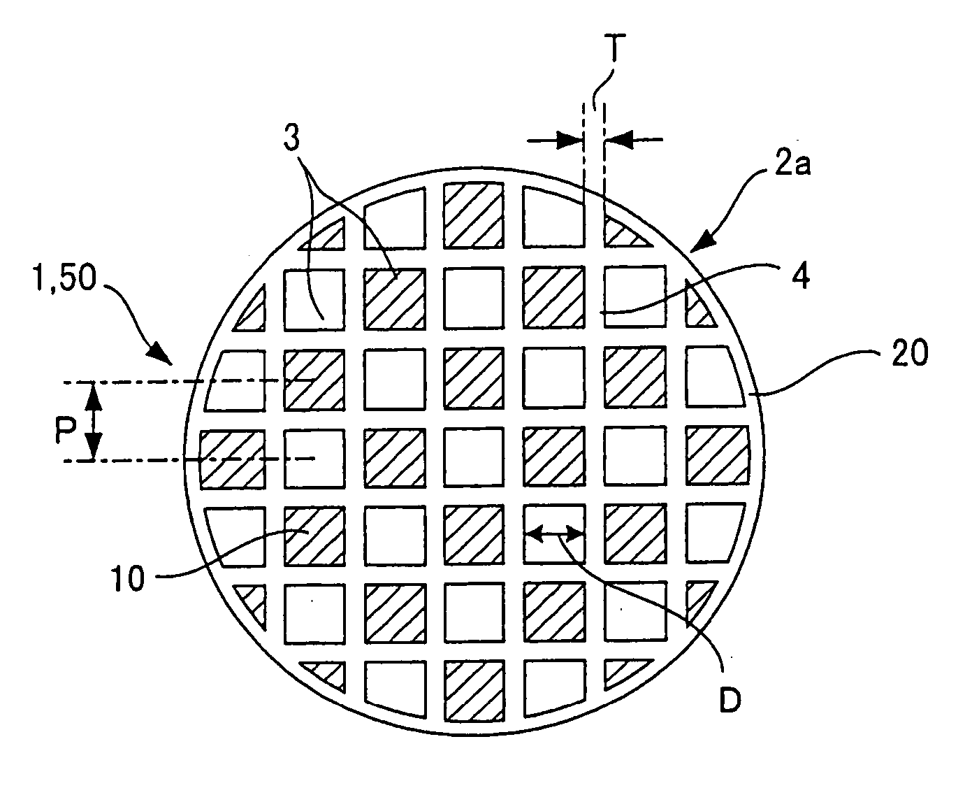
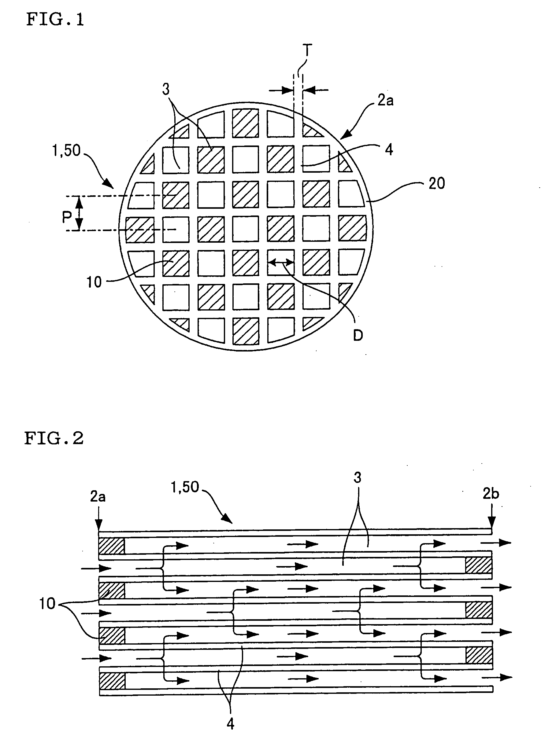
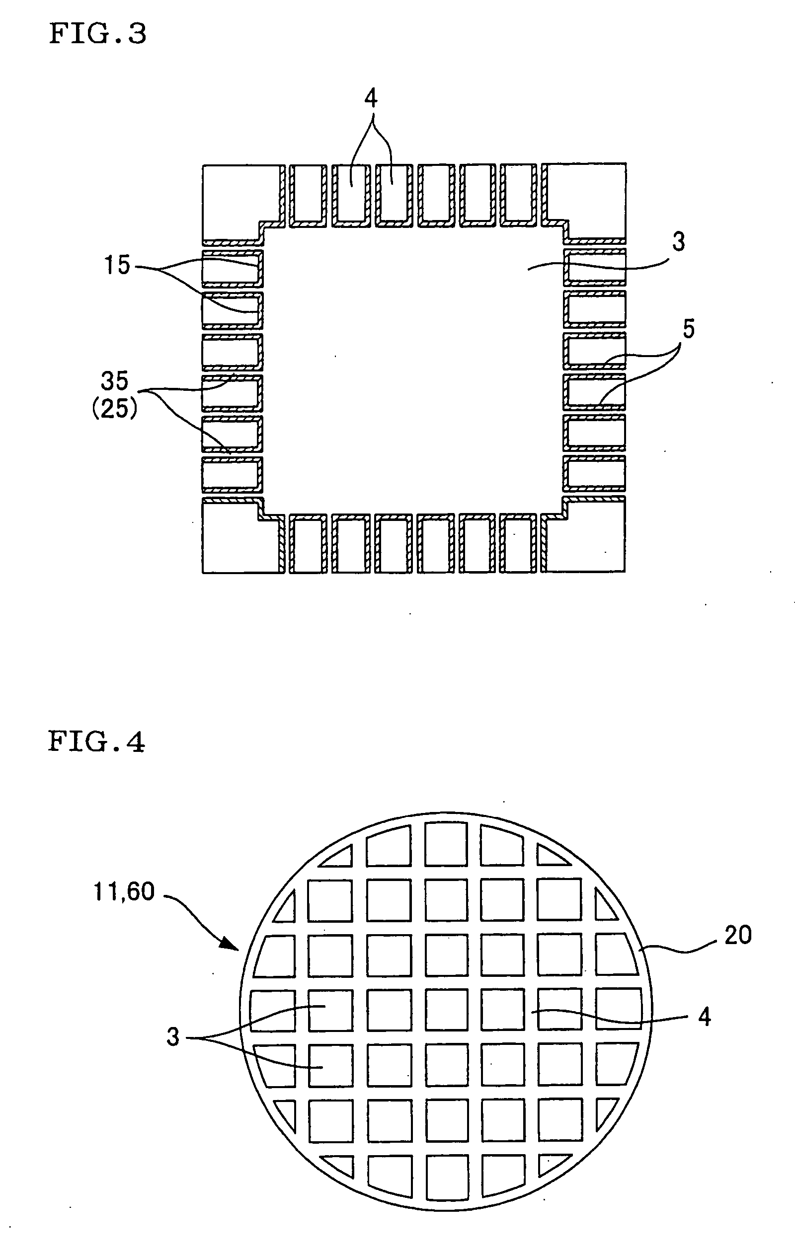
TECHNICAL FIELD [0001] The present invention relates to a honeycomb structure and a honeycomb catalyst structure both suitably used for purification of to-be-purified components such as carbon monoxide (CO), hydrocarbons (HC), nitrogen oxides (NOx), sulfur oxides (SOx) and the like, contained in the exhaust gases emitted from automobile engines, construction equipment engines, industrial stationery engines, combustion equipment, etc. BACKGROUND ART [0002] Currently, catalysts having a honeycomb structure (hereinafter referred to as honeycomb catalyst structures) are in use in order to purify the exhaust gases emitted from engines, etc. These honeycomb catalyst structures have a construction, as shown in FIG. 6, of partition walls 4 defining cells 3 and a catalyst layer 15 carried on the surface of partition walls 4. As shown in FIGS. 4 and 5, when an exhaust gas is purified using a honeycomb catalyst structure 60 (a honeycomb structure 11), the exhaust gas is allowed to flow into ea...

Claims


Application Information

Patent Timeline
Patent Type & Authority Applications(United States)
IPC IPC(8): B32B3/12
CPCB01D39/2051Y10T428/24157B01D46/2429B01D46/2444B01D46/2451B01D46/2455B01D46/2459B01D46/2466B01D46/247B01D46/2474B01D2046/2433B01D2046/2496B01D2239/0471B01J23/40B01J23/63B01J35/04B01J37/0215C04B35/10C04B35/14C04B35/185C04B35/195C04B35/46C04B35/478C04B35/565C04B35/584C04B35/597C04B38/0009C04B2111/00129C04B2111/00793C04B2111/0081F01N3/2828F01N2330/30F01N2330/48B01D39/2093Y10T428/24149Y02T10/22C04B38/0051C04B38/0074C04B35/48C04B38/0054Y02T10/12B01D46/24491B01D46/2498B01D46/2484B01D46/24494B01D46/2482B01D46/24492B01D46/2425
Inventor MIYAIRI, YUKIONODA, NAOMIMIZUNO, YUKIO
Owner NGK INSULATORS LTD
Why Eureka
Try Eureka