Photovoltaic cell comprising carbon nanotubes formed by electrophoretic deposition and method for fabricating the same

a photovoltaic cell and carbon nanotube technology, applied in the field of photovoltaic cells, can solve the problems of reducing the power conversion efficiency, reducing the practical application and improvement of affecting the efficiency of silicon photovoltaic cells, so as to improve the electron transfer performance and increase the power conversion efficiency

Inactive Publication Date: 2007-03-15
SAMSUNG ELECTRONICS CO LTD
View PDF2 Cites 29 Cited by
  • Summary
  • Abstract
  • Description
  • Claims
  • Application Information

AI Technical Summary

Benefits of technology

[0012] Therefore, the present invention solves the above problems of the prior art by providing a photovoltaic cell with improved electron transfer performance and increased power conversion efficiency wherein a separate carbon nanotube layer is stacked on a semiconductor layer so as to maintain the inherent characteristics of carbon nanotubes.

Problems solved by technology

However, since silicon photovoltaic cells incur considerable fabrication costs, there are some limitations in the practical application and improvement in the efficiency of the silicon photovoltaic cells.
However, not all of the excited electrons are transferred to the conduction band of the metal oxide 105, since some electrons are bonded with the dye molecules to return to the ground state and some electrons transferred to the conduction band cause recombination reactions, e.g., participation in redox coupling inside the electrolyte, to lower the power conversion efficiency, which becomes a cause of reduction in electromotive power.
(see FIG. 2), at which collapse of the carbon nanotubes happens, or higher for a long time, the carbon nanotubes are severely damaged.
This damage poses problems that the desired effects cannot be attained, uniform dispersion of the carbon nanotubes is difficult, and application to flexible substrates, e.g., plastic substrates, is impossible.

Method used


Image

  • Photovoltaic cell comprising carbon nanotubes formed by electrophoretic deposition and method for fabricating the same
  • Photovoltaic cell comprising carbon nanotubes formed by electrophoretic deposition and method for fabricating the same
  • Photovoltaic cell comprising carbon nanotubes formed by electrophoretic deposition and method for fabricating the same

Examples


example 1

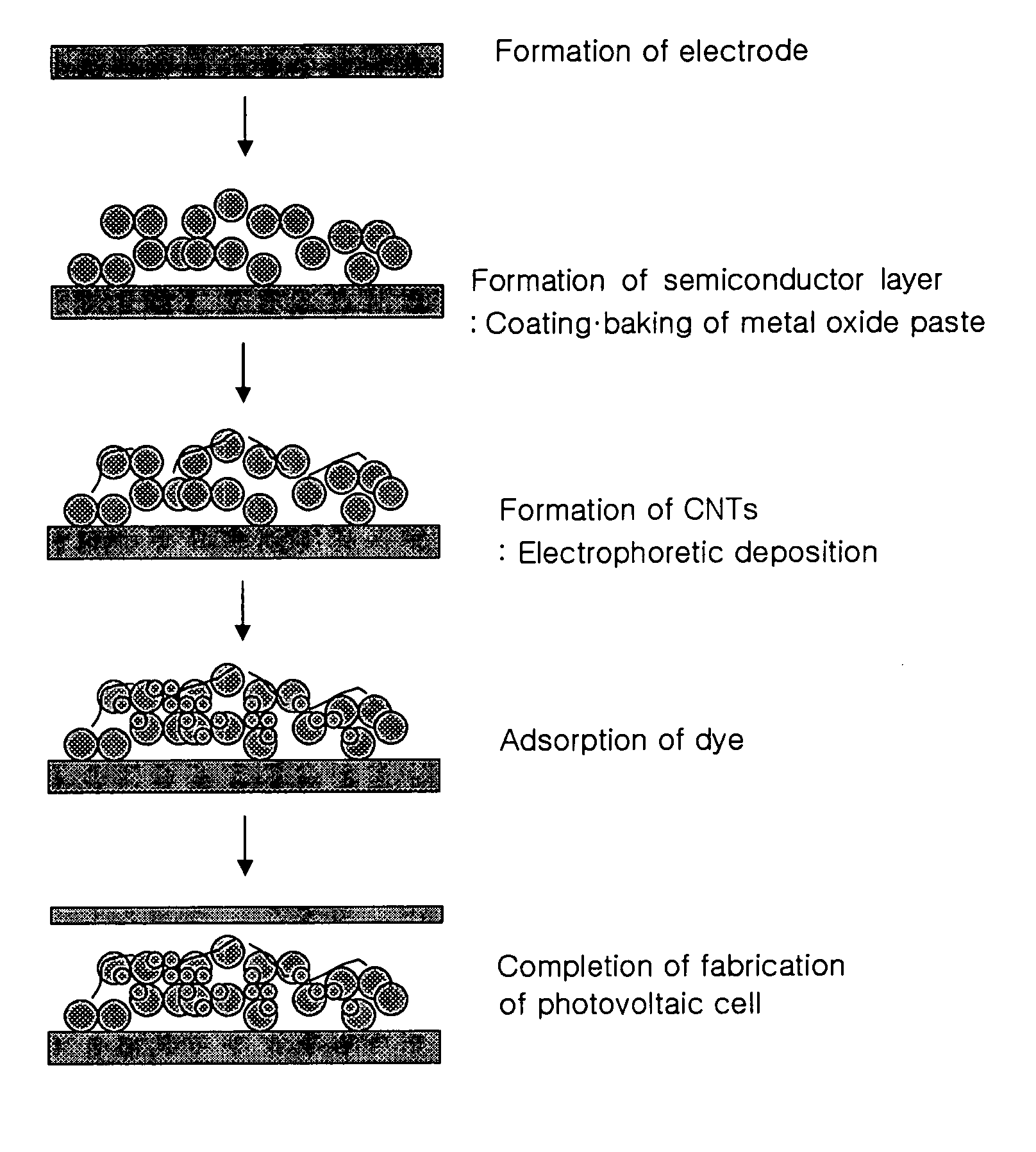
[0086] Fluorine-doped tin oxide (“FTO”) was applied to a glass substrate using a sputter, and then a paste of TiO2 particles having a particle diameter of 13 nm was applied thereto by screen printing. The resulting substrate was baked at 450° C. for 30 minutes to form a porous TiO2 film having a thickness of about 15 μm. Separately, carbon nanotubes were treated with HCl, HNO3, and the like, and dispersed in MgO.H2O for 0.5 hours to form an ionic state. The carbon nanotubes in an ionic state were attached to the TiO2 film by applying a voltage of 0.006 V / μm for 30 seconds in accordance with electrophoretic deposition. FIG. 8 is a scanning electron micrograph (“SEM”) showing the surface of the TiO2 layer on which the carbon nanotubes are deposited. Referring to FIG. 8, the carbon nanotubes are formed on the surface of the TiO2 layer. Subsequently, the resulting structure was dipped in a 0.3 mM ruthenium dithiocyanate 2,2′-bipyridyl-4,4′-dicarboxylate solution for 24 hours, and dried ...

example 2

[0088] A photovoltaic cell was fabricated in substantially the same manner as in Example 1, except that a TiO2 bilayer was formed by forming a 3 μm thick TiO2 layer using a paste of TiO2 particles having a diameter of 13 nm, and forming a 12 μm thick TiO2 layer thereon using a paste of TiO2 particles having a diameter of 300 nm. FIG. 9 is a cross-sectional scanning electron micrograph (“SEM”) of the photovoltaic cell.

example 3

[0089] A photovoltaic cell was fabricated in substantially the same manner as in Example 1, except that the electrophoretic deposition was performed by applying a voltage of 0.006 V / μm for 60 seconds to form a carbon nanotube layer.


PUM

PropertyMeasurementUnit
particle sizeaaaaaaaaaa

Abstract

A photovoltaic cell includes carbon nanotubes formed by electrophoretic deposition. A separate carbon nanotube layer is stacked on a semiconductor layer by electrophoretic deposition, or a mixed layer of carbon nanotubes and a constituent material of a semiconductor layer is formed by electrophoretic deposition, thereby preventing damage to the carbon nanotubes. A method for fabricating the photovoltaic cell is also provided. Since superior electrical conductivity of the carbon nanotubes is maintained unchanged, the photovoltaic cell exhibits improved electron transfer performance and inhibits accumulation of electrons and occurrence of recombination reactions.

Description

[0001] This application claims priority to Korean Patent Application No. 2005-84713, filed on Sep. 12, 2005 and all the benefits accruing therefrom under 35 U.S.C. §119, and the contents of which in its entirety are herein incorporated by reference. BACKGROUND OF THE INVENTION [0002] 1. Field of the Invention [0003] The present invention relates to a photovoltaic cell including carbon nanotubes (“CNTs”) formed by electrophoretic deposition and a method for fabricating the photovoltaic cell. More particularly, the present invention relates to a photovoltaic cell with improved electron transfer performance and high power conversion efficiency and including CNTs, and a method for fabricating the photovoltaic cell. [0004] 2. Description of the Related Art [0005] In recent years, numerous studies have focused on various alternative energy sources for conventional fossil fuels to solve urgent energy consumption problems. Particularly, extensive research into effective utilization of natur...

Claims


Application Information

Patent Timeline
Patent Type & Authority Applications(United States)
IPC IPC(8): H01L31/00
CPCB82Y10/00H01G9/2031Y02E10/542H01L51/0086H01L51/0048H10K85/221H10K85/344H01L31/04H01L31/18
Inventor PARK, YOUNG JUNNAM, JUNG GYUKIM, JIN YOUNG
Owner SAMSUNG ELECTRONICS CO LTD
Why Eureka
Try Eureka