Non-fouling polymeric surface modification and signal amplification method for biomolecular detection

Active Publication Date: 2007-03-29
DUKE UNIV
View PDF23 Cites 31 Cited by
  • Summary
  • Abstract
  • Description
  • Claims
  • Application Information

AI Technical Summary

Benefits of technology

[0030] An advantage of the foregoing methods is the variety of techniques by which the detecting step can be carried out. For example, the detecting step may be carried out by: (a) ellipsometry; (b) surface plasmon resonance (SPR); (c) localized surface plasmon resonance using noble metal nanoparticles in solution or on a transparent surface; (d) surface acoustic wave (SAW) devices; (e) quartz-crystal microbalance with dissipation (QCM-D) (e) atomic force microscopy, (f) detection of radiolabeled nucleotides incorporated in the elongated portion for radioactive detection, (g) detection of stable isotope lab

Problems solved by technology

The modification of silicon oxide to modulate protein and cell interactions has proven to challenging for a number of technical reasons: 1) the formation of silane self-assembled monolayers (SAMs), the most common route to functionalize glass and other metal oxides, is complicated by the sensitivity of most silanes to humidity and their propensity to form polymeric multi-layers (Wasserman, Tao et al.
2002) have been taken to solve this problem, but only with limited success.
3) It is also difficult to stamp silanes onto glass with the ease and reproducibility with which alkanethiols can be patterned by micro-contact printing and other soft lithography methods so that the patterning of PEG on to glass by soft lithography has only been marginally successful (Xia, Mrksich et al.
Finally, for the class of sensors that incorporate an amplification step prior to or during generation of the detected signal, the effective elimination of adventitious adsorption or binding of biomolecules or other reagent

Method used


Image

  • Non-fouling polymeric surface modification and signal amplification method for biomolecular detection
  • Non-fouling polymeric surface modification and signal amplification method for biomolecular detection
  • Non-fouling polymeric surface modification and signal amplification method for biomolecular detection

Examples


Embodiment Construction

[0043] The present invention will now be described more fully hereinafter with reference to the accompanying drawings, in which preferred embodiments of the invention are shown. This invention may, however, be embodied in different forms and should not be construed as limited to the embodiments set forth herein. Rather, these embodiments are provided so that this disclosure will be thorough and complete, and will fully convey the scope of the invention to those skilled in the art.

[0044] Unless otherwise defined, all technical and scientific terms used herein have the same meaning as commonly understood by one of ordinary skill in the art to which this invention belongs.

[0045] The disclosures of all United States patents cited herein are incorporated by reference in their entirety.

1. Definitions.

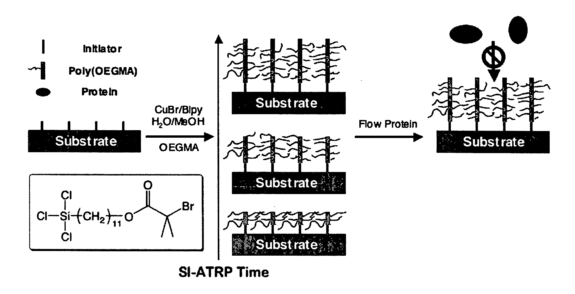
[0046]“SI-ATRP” as used herein means surface initiated atom transfer radical polymerization.

[0047]“OEGMA” as used herein refers to oligo(ethylene glycol)methyl methacrylate.

[0048]“Biol...


PUM

PropertyMeasurementUnit
Lengthaaaaaaaaaa
Densityaaaaaaaaaa

Abstract

An article such as a biosensor having a nonfouling surface thereon is described. The article comprises: (a) a substrate having a surface portion; (b) a linking layer on the surface portion; (c) a polymer layer comprising brush molecules formed on the linking layer; and (d) optionally but preferably, a first member of a specific binding pair (e.g., a protein, peptide, antibody, nucleic acid, etc.) coupled to the brush molecules. The polymer layer is preferably formed by the process of surface-initiated polymerization (SIP) of monomeric units thereon. Preferably, each of the monomeric units comprises a monomer (for example, a vinyl monomer) core group having at least one protein-resistant head group coupled thereto, to thereby form the brush molecule on the surface portion. Methods of using the articles are also described.

Description

RELATED APPLICATIONS [0001] This application claims the benefit of U.S. Provisional Patent Application Ser. No. 60 / 717,430; filed Sep. 15, 2005, the disclosure of which is incorporated by reference herein in its entirety. [0002] This application is related to Ashutosh Chilkoti and Hongwei Ma, A tunable nonfouling surface of oligoethylene glycol, U.S. patent application Ser. No. 10 / 783,054, filed Feb. 20, 2004 (Docket No. 5405-318), the disclosure of which is incorporated by reference herein in its entirety.[0003] This invention was made with Government support under grant no. R01 CI-00097 from the Centers for Disease Control / NCID. The United States Government has certain rights to this invention.FIELD OF THE INVENTION [0004] This invention relates to a non-fouling polymeric surface modification and signal amplification method for ultra-sensitive biomolecular detection. BACKGROUND OF THE INVENTION [0005] Glass and silicon oxide are widely used substrates for biosensors, clinical immu...

Claims


Application Information

Patent Timeline
IPC IPC(8): C12Q1/68
CPCB01J19/0046G01N33/5302B01J2219/00596B01J2219/00605B01J2219/00608B01J2219/0061B01J2219/00612B01J2219/00626B01J2219/00628B01J2219/0063B01J2219/00635B01J2219/00637B01J2219/00659B01J2219/00677B01J2219/00722B01J2219/00725B01J2219/0074B82Y15/00B82Y30/00C12Q1/6837C40B50/18G01N33/54393B01J2219/00432C12Q2525/313C12Q2521/131C12Q1/682G01N33/54353
Inventor CHILKOTI, ASHUTOSH
Owner DUKE UNIV
Why Eureka
Try Eureka