Process and apparatus for the hydrogenation of chlorosilanes

a chlorosilane and hydrogenation technology, applied in mechanical equipment, machines/engines, silicon compounds, etc., can solve the problems of increased corrosion of components and high thermal stress on components, and achieve the effect of simple operation

Active Publication Date: 2007-03-29
WACKER CHEM GMBH
View PDF12 Cites 41 Cited by
  • Summary
  • Abstract
  • Description
  • Claims
  • Application Information

AI Technical Summary

Benefits of technology

[0007] It is an object of the invention to provide a process for the hydrogenation of chlorosilanes which avoids introduction of impurities into the reaction and can be operated more simply and / or in a more energy-efficient manner than known processes which avoid such contamination. These and other objects are achieved by a process for the hydrogenation of a chlorosilane in a reactor comprising a reaction chamber having a surface which comes into contact with the chlorosilane and a heating element which is heated by direct passage of electric current and has a surface which comes into contact with the chlorosilane, with the reaction chamber and the heating element comprising graphite, wherein an Si-containing compound and hydrogen are brought into contact with the surface of the reaction chamber and the surface of the heating element in such a way that an SiC coating is formed in situ on the surface of the reaction chamber and the surface of the heating element in a first process step and hydrogenation of the chlorosilane is effected by heating of a chlorosilane / hydrogen mixture in the reaction chamber by means of the heating element in a second process step, with the first process step being carried out at a reaction temperature which is higher than the reaction temperature in the second process step.

Problems solved by technology

A higher reactor temperature results in further undesirable effects such as high thermal stress on the components and heating elements, increased corrosion of the components caused by chemical attack by hydrogen, chlorosilanes and HCl, and also deposition of silicon at undesirable places.

Method used


Image

  • Process and apparatus for the hydrogenation of chlorosilanes
  • Process and apparatus for the hydrogenation of chlorosilanes

Examples


example 1

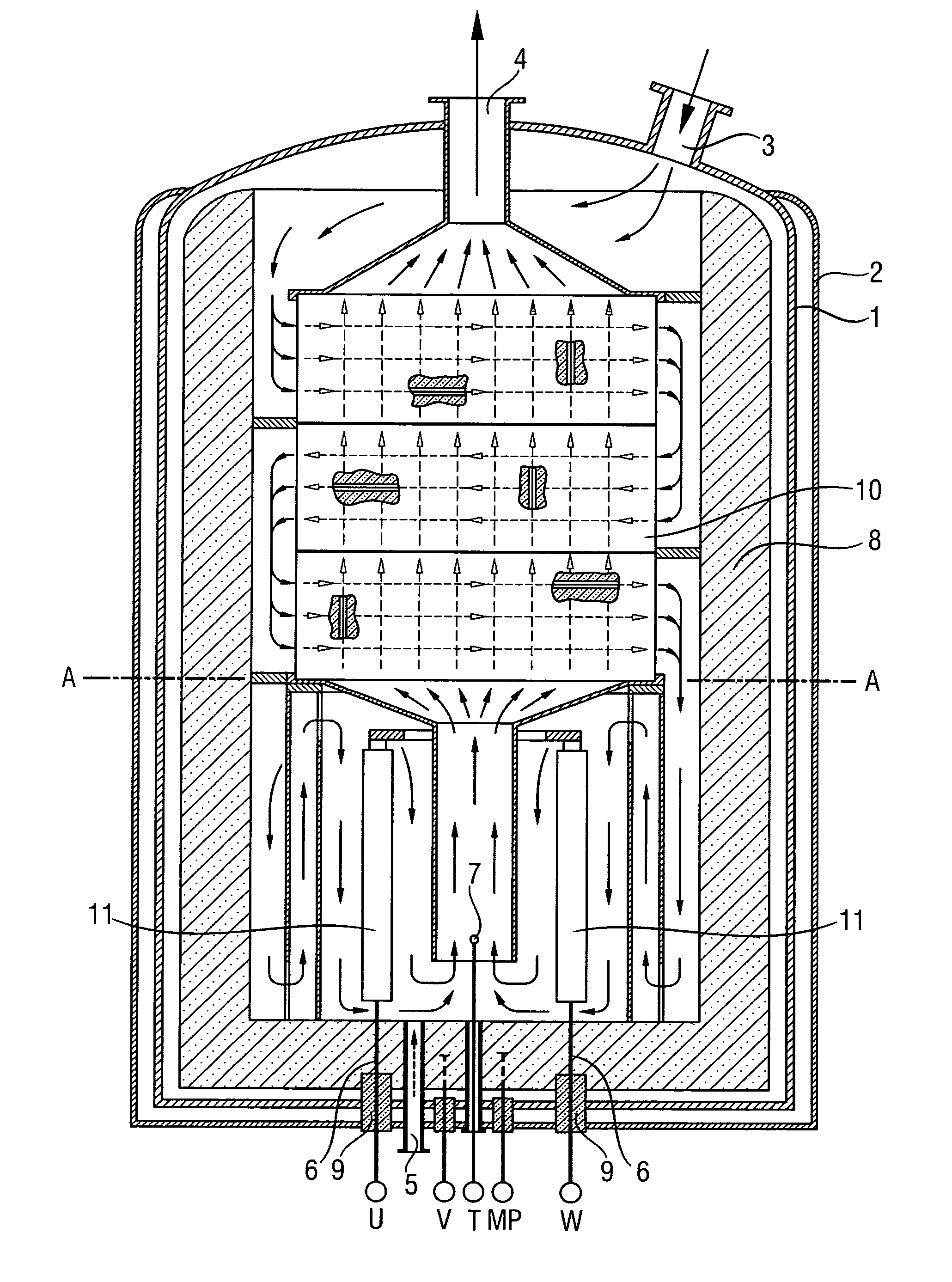
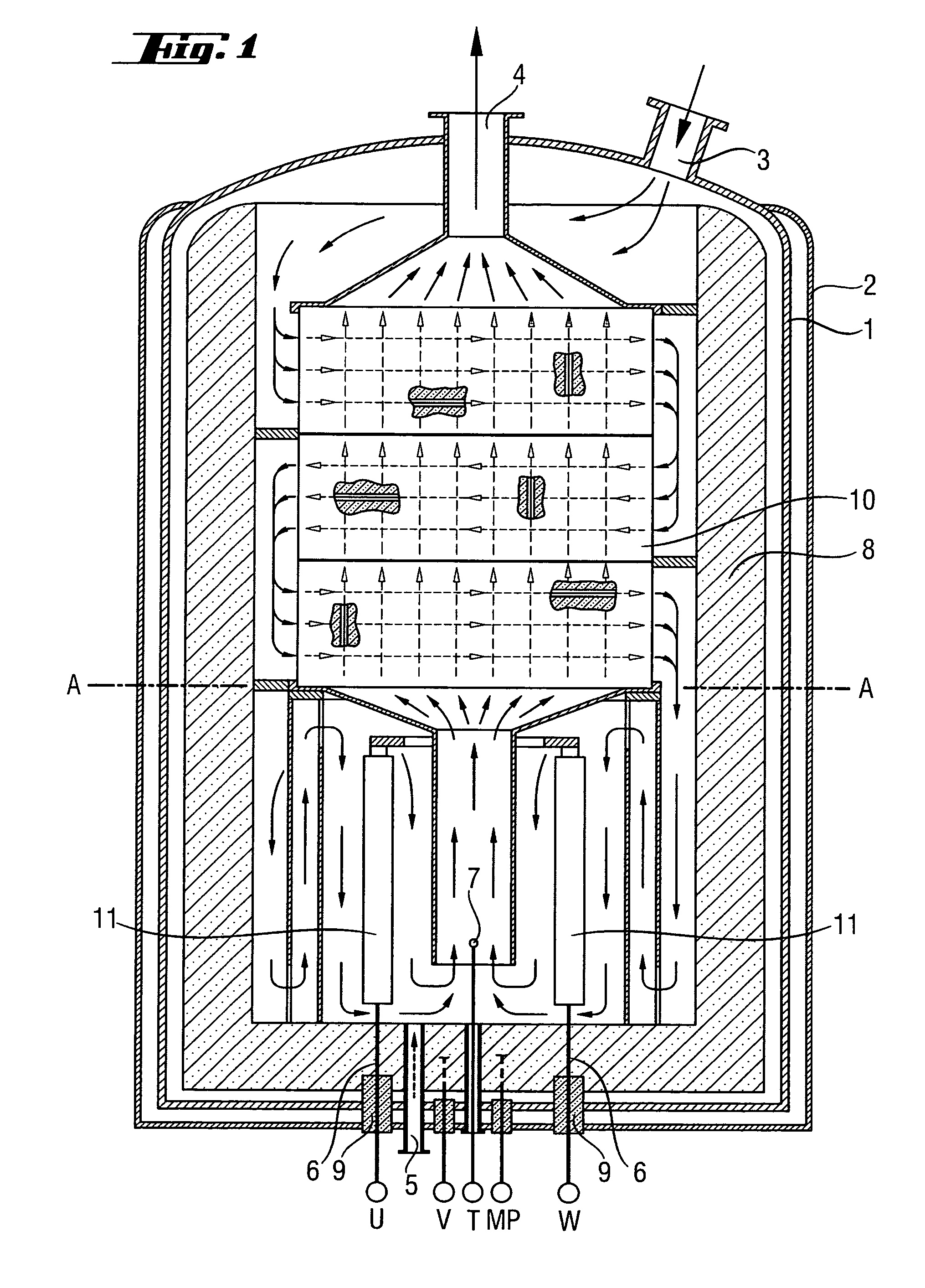
[0043] Coating using a chlorosilane / H2 mixture was carried out as first process step in a reactor as shown in FIG. 1. The progress of the coating process was monitored by means of the change of the resistance of the heating elements. The reactor was firstly brought to the target temperature (1300° C.) at a hydrogen throughput of 150 m3 / h at only a slightly superatmospheric pressure (1.5 bar). The chlorosilane was then fed in. Over a period of 48 hours, the throughput of hydrogen was increased to 1500 m3 / h and that of chlorosilane was increased to 5 metric t / h. Over this time, the pressure was increased to 6 bar. Silicon tetrachloride and purified hydrogen from the synthesis of TCS were used as starting materials.

[0044] The coating process was stopped after about 72 hours. Test specimens were taken and examined in terms of their chemical resistance as described in Example 3.

[0045] The thickness of the SiC layer on the structural elements was 10-100 μm (depending on the temperature ...

example 2

[0046] A reactor which had been coated as described in Example 1 and, for comparative purposes, a reactor with uncoated graphite components as was used in Example 1 were used under the following conditions for the hydrogenation of SiCl4: Reactor temperature 900° C., pressure 5 bar, molar ratio of H2:SiCl4=2:1, SiCl4 throughput 8 metric t / h.

[0047] The reactor with the uncoated components had to be shut down after a period of operation of less than 6 months. The reactor with the coated components was shut down after 12 months. The two reactors were compared after the end of the period of operation. The uncoated components displayed considerable corrosion and had to be discarded. The coated components showed barely any corrosion and could be reused for the next period of operation. The operating life of the coated reactor components had more than doubled compared to the components of the comparative reactor; the specific energy consumption per amount of TCS produced had been reduced b...

example 3

[0048] The test specimens which had been coated in situ in the reactor (see Example 1) were compared with other test specimens. For this purpose, test specimens made of various materials were introduced into a reactor as shown in FIG. 1 in order to examine their chemical resistance under the conditions of the hydrogenation of SiCl4 (1000° C., H2:SiCl4=2:1, duration of experiment 3 months).

[0049] The chemical resistance was estimated from the changes in the surface structure and the loss in mass of the test specimens. The results are summarized in Table 1.

TABLE 1Test specimensWeight changeSurfaceGraphite parts coated in+2.1%unchangedsitu from Example 1SiC-precoated graphite+0.9%unchangedpartsGraphite+24% (due to SiSiC depositionuptake)Graphite / graphite−40% (part Si uptake,SiC depositionfiberspart decomposition)Ceramic based−100%Completelyon SiO2decomposedCeramic based−100%Completelyon Al2O3decomposed

No difference was found between the chemical resistance of the test specimens pre...


PUM

PropertyMeasurementUnit
temperatureaaaaaaaaaa
pressureaaaaaaaaaa

Abstract

Hydrogenation of a chlorosilane takes place in a reactor having a graphite reaction chamber with a surface which contacts the chlorosilane and a graphite electric heating element which also contacts the chlorosilane, wherein an Si-containing compound and hydrogen are contacted with the reaction chamber and the heating element such that an SiC coating is formed in situ on their surfaces in a first process step, and hydrogenation of the chlorosilane is effected by heating of a chlorosilane/hydrogen mixture in the reaction chamber by means of the heating element in a second process step, the first process step carried out at a reaction temperature which is higher than the reaction temperature of the second process step.

Description

BACKGROUND OF THE INVENTION [0001] 1. Field of the Invention [0002] The invention relates to a process and an apparatus for the hydrogenation of chlorosilanes. [0003] 2. Background Art [0004] Processes for the hydrogenation of chlorosilanes at temperatures of >600° C. are known. For example, the hydrogenation of silicon tetrachloride (STC) to trichlorosilane (TCS) has great importance, since large amounts of STC are obtained as by-product in the chemical vapor deposition of semiconductor silicon and STC can be converted back into TCS starting material by means of these processes. Such processes are described, for example, by U.S. Pat. No. 5,422,088 (Burgie et al.), U.S. Pat. No. 3,933,985 (Rogers), U.S. Pat. No. 4,217,334 (Weigert et al.), U.S. Pat. No. 4,536,642 (Hamster et al.) and also by the references cited in these documents. [0005] In all these processes, graphite is used as material of construction for the reactor components, insulation material and heating elements becau...

Claims


Application Information

Patent Timeline
Patent Type & Authority Applications(United States)
IPC IPC(8): C07F7/00
CPCC01B33/1071F01N3/0253F01N2610/03F01N2260/02F01N2260/024F01N3/36
Inventor PAETZOLD, UWEREISBECK, ANTONSURNER, MANFRED
Owner WACKER CHEM GMBH
Why Eureka
Try Eureka