Process for reducing contaminants in condensate resulting from the conversion of bauxite to alumina

a technology of bauxite and condensate, which is applied in the direction of filtration treatment, multi-stage water/sewage treatment, separation process, etc., can solve the problems of deleterious contaminants, inability to successfully remove contaminants from process water and condensates, and inability to achieve effective removal methods. achieve the effect of rapid treatment tim

Inactive Publication Date: 2007-04-12
DEWITT DICK DOUGLAS B +4
View PDF1 Cites 0 Cited by
  • Summary
  • Abstract
  • Description
  • Claims
  • Application Information

AI Technical Summary

Benefits of technology

[0028] The process is particularly useful, because impurities can be removed from the condensate without any substantial reduction in the heat capacity of the condensate. The heat capacity in some cases exceeds one million BTU's per 1,000 gallons of condensate.
[0029] The process can be carried out on-line with negligible heat loss. The time it takes for the contaminated water to enter the treatment and leave the treatment process is approximately 1 to 15 minutes depending upon the total process required and flow. It is because of this rapid treatment time that the temperature of the condensate can be maintained before it is re-used.

Problems solved by technology

The process water often comes into contact with a variety of contaminants when the industrial process is carried out.
These contaminants remain in the process water.
Although there may be many contaminants in the process water and they vary depending upon the type of industrial process carried out, the more deleterious contaminants include suspended solids, oil and grease, metals, and silicate compounds.
Although there are many methods known for removing contaminants from aqueous systems, these methods cannot be successfully used to remove contaminants from process water and condensates, particularly without reducing the heat capacity of the process water and / or condensate.
The temperature of the condensate typically ranges from about 80° C. to 100° C., most typically from 95° C. to 100° C. What makes it difficult to purify the condensate is the presence of suspended solids, which can be 1000 times as high as that found in other contaminated aqueous systems.
Because the temperature is elevated, it is difficult to purify condensate, particularly without reducing the heat capacity of the condensate.
Additionally, the difficulty is compounded because the condensate may have high alkalinity, which increases the stability of the emulsion of oil found in the process water and / or condensate.
The elevated temperature and high alkalinity of the condensate also impairs the usefulness of chemicals typically used to break the emulsion, and / or coagulate suspended solids.
Thus, many processes that could be used to purify condensate are not compatible with the high temperatures and alkalinity.
This condensate is often waste because contains small amounts of aluminum, iron, silica, caustic, and organics.
The contamination is caused by carryover of effluent liquor into the flashed steam.
However, if utilized without treatment, the boilers would exhibit frequent failures, which would result because of the precipitation of impurities.
Because there is no effective and economical way of removing the impurities from the condensate, the condensate is frequently wasted.
The problem with using these ion exchange resins is that anion resins are not thermally stable at temperatures greater than 140° F. in the OH form.
This means the resin rapidly deteriorates over a period of weeks or months so that strong base anion resin rapidly looses the ability to remove silica.
Since ASME feedwater guidelines for silica are <0.1 ppm at boiler operating pressures frequently found in Alumina refineries this means that even if filtered and cleaned, the condensate cannot be used unless cooled.
Cooling of course reduces the heat savings which is the primary reason for recovering digestion and evaporation condensates.

Method used


Image

  • Process for reducing contaminants in condensate resulting from the conversion of bauxite to alumina
  • Process for reducing contaminants in condensate resulting from the conversion of bauxite to alumina
  • Process for reducing contaminants in condensate resulting from the conversion of bauxite to alumina

Examples


examples

[0065] While the invention has been described with reference to a preferred embodiment, those skilled in the art will understand that various changes may be made and equivalents may be substituted for elements thereof without departing from the scope of the invention. In addition, many modifications may be made to adapt a particular situation or material to the teachings of the invention without departing from the essential scope thereof. Therefore, it is intended that the invention not be limited to the particular embodiment disclosed as the best mode contemplated for carrying out this invention, but that the invention will include all embodiments falling within the scope of the appended claims. In this application all units are in the metric system and all amounts and percentages are by weight, unless otherwise expressly indicated.

example

Removal of Contaminants from Condensate Generated by the Bayer Process for Producing Alumina

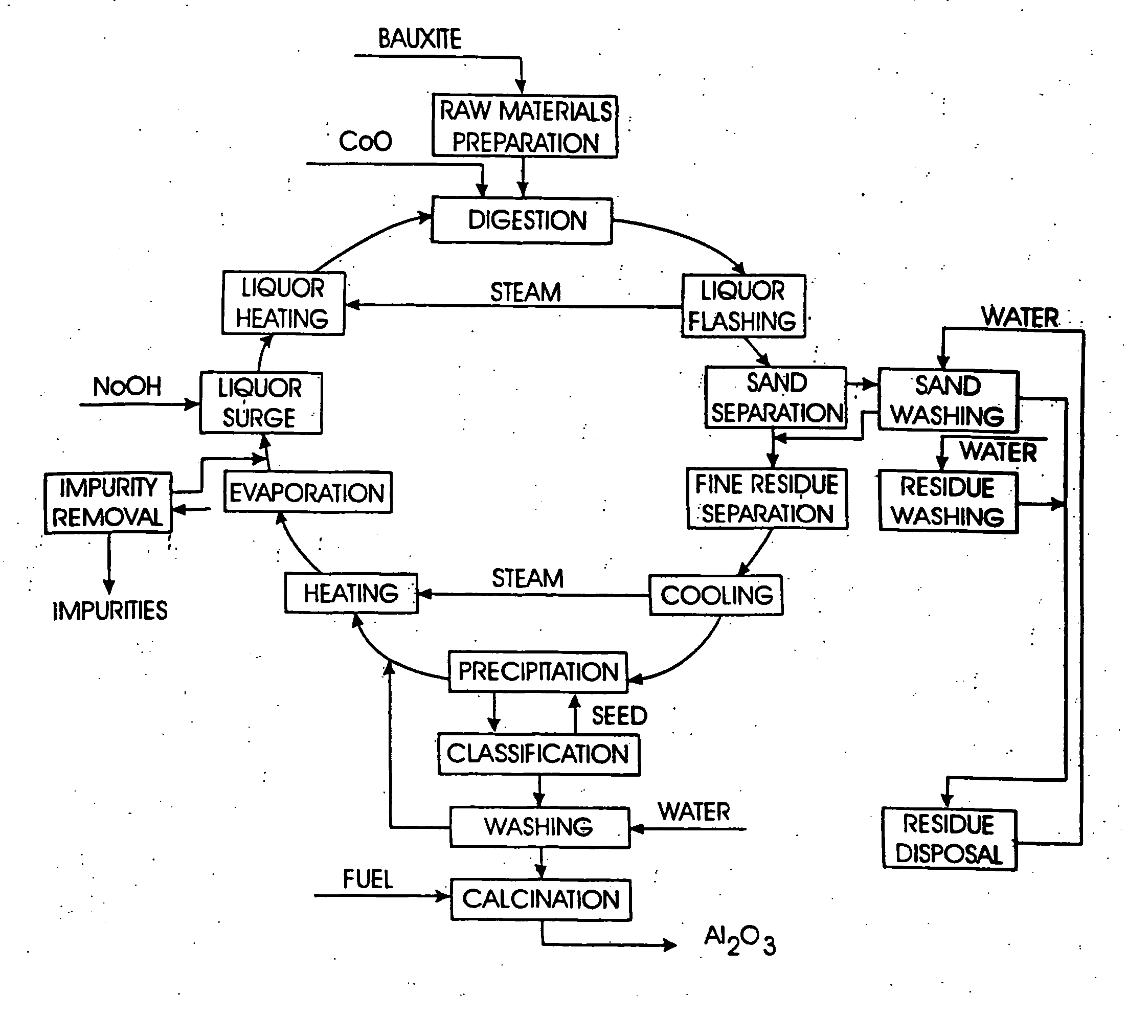
[0066] This example illustrates how the process is used to remove contaminants from the digester process water (DPW) and the evaporator process condensate (EPC), generated by the Bayer process for producing alumina. The alumina is produced from bauxite by the Bayer process as shown FIG. 1. The temperature of the DPW is from about 80° C. to about 100° C. and the temperature of the EPC is from about 80° C. to about 100° C. The flow rate for the condensate tested is approximately 60 GPM and tests are conducted for about a month. The sample is piped from the process and the purification took place done on-line.

[0067] Twenty ppm of MFC are added to samples of the DPW and the EPC. Ten seconds later, 15 ppm of TAC are added to the DPW and the EPC, which is treated with the melamine formaldehyde emulsion breaker. The condensate is then filtered using FILTER.

[0068] After filtration the condensate i...


PUM

PropertyMeasurementUnit
temperatureaaaaaaaaaa

Abstract

This invention relates to a process for reducing the contaminants in condensate resulting from the conversion of bauxite to alumina. The process involves coagulating solids in the condensate, filtering the condensate, and then purifying the condensate with a cation exchange resin and an anion exchange resin.

Description

CLAIM TO PRIORITY [0001] This application claims the benefit of U.S. Provisional Application No. 60 / 715,906 filed on Sep. 9, 2005, the contents of which are hereby incorporated into this application.TECHNICAL FIELD OF THE INVENTION [0002] The invention relates to a process for reducing the contaminants in condensate resulting form the conversion bauxite to alumina. The process involves coagulating solids in the condensate, filtering the condensate, and then purifying the condensate with a cation exchange resin and an anion exchange resin. BACKGROUND OF THE INVENTION [0003] There are many industrial process that use process water in carrying out reactions, as an effluent for removing unwanted by-products, as a diluent, and for many other functions. Examples of industrial processes, which use process water, include, for example, the refining of petroleum; the production of olefins, polymers, and organic acids; the production of metals, e.g. aluminum, iron, steel, and copper; and the b...

Claims


Application Information

Patent Timeline
Patent Type & Authority Applications(United States)
IPC IPC(8): C02F1/42
CPCB01J39/04B01J47/04C01F7/06C02F1/5236C02F1/56C02F9/00C02F2103/16B01J41/04C02F1/001C02F1/42
Inventor DEWITT-DICK, DOUGLAS B.RAMHARACK, BACHANSPENCE, RUSSELL P.BADGER, EDWARD W.HILDEBRAND, LYNN N.
Owner DEWITT DICK DOUGLAS B
Why Eureka
Try Eureka