Continuous reversible gear shifting mechanism

a gear shifting mechanism and reversible technology, applied in the field of communication, can solve the problems of limiting the pll settling time to typically no less than a hundred s, severe slowdown of the loop dynamics, and large current consumption, so as to narrow the loop bandwidth, widen the loop bandwidth, and increase the loop gain

Active Publication Date: 2007-04-19
TEXAS INSTR INC
View PDF8 Cites 53 Cited by
  • Summary
  • Abstract
  • Description
  • Claims
  • Application Information

AI Technical Summary

Benefits of technology

[0011] The present invention is a gear shifting mechanism that is operative to adjust the loop gain of a phase locked loop (PLL) circuit. The mechanism is adapted for use in the loop filter circuit of a PLL loop and is capable of changing the loop gain in both a continuous and reversible manner. The loop gain can be increased to widen the bandwidth of the loop and can also be decreased to narrow the loop bandwidth. The gear shift mechanism comprises an α gear shift circuit, a ρ gear shift circuit and an optional IIR gear shift circuit. The α gear shift circuit comprises an attenuator which enables hitless operation of the PLL loop at the occurrence of gear shift events. The α gear shift circuit comprises an accumulator whose output is multiplied by the gain value ρ. The invention enables multiple gear shifts in either positive or negative direction to be achieved by configuring the loop gain variables α and ρ which may be accomplished in software.
[0012] The gear shift mechanism of the invention thus aids in enabling systems to achieve sufficient RF performance (e.g., RMS and peak phase error, error vector magnitude, EVM) and fast lock time to meet the requirements of many modem wireless standards. The ability to gear shift in the reverse direction (i.e. making the PLL loop faster) enables the system to handle sudden frequency deviations, which is useful in certain modulation schemes such as WCDMA, as well as sudden frequency perturbations such as those typically occurring in a handheld phone environment. In an implementation of the invention adapted for GSM, the ADPLL settled to the GSM frequency error within 15 μs, an order of magnitude faster than prior art solutions.
[0013] The invention provides a novel technique which can be used in the framework of an ADPLL to maximally speed up (by at least an order of magnitude) the acquisition of new channel frequencies. Using the gear shifting mechanism of the present invention in an ADPLL incorporating a DCO and associated varactor banks, the loop can start with an ultra-wide acquisition bandwidth and progressively narrow it down while traversing through finer DCO varactor banks. The fully digital implementation of the invention guarantees hitless bandwidth switching through the entire acquisition interval. Furthermore, since the oscillator control is fully digital, the last known control word for a given channel could be preloaded to reduce the initial frequency error.

Problems solved by technology

Traditionally, it has been based on a charge-pump PLL which is not easily amenable to scaled CMOS integration and suffers from high level of reference spurs generated by the correlative phase detection method.
An important issue in frequency synthesis for today's wireless applications is the acquisition or settling time to a new channel frequency from the trigger event to the instance when the wireless terminal is ready to transmit or receive with the specified low level of frequency error, phase noise and spurious tones.
Unfortunately, it also severely slows down the loop dynamics.
This difficulty in performing the PLL bandwidth switchover or gear shifting limits the PLL settling time to typically no less than a hundred μs, as is the case in many currently available commercial handset RF transceivers.
One prior art base station PLL exhibits a 10 μs settling time but this was achieved by means of large area, high complexity and large current consumption.
A change in loop gain, however, typically causes an undesirable frequency step in the oscillator output.
Typically, it is difficult to perform PLL gear shifting in analog circuits because of the imperfect matching and voltage or charge losses during switching which results in phase hits whenever a sudden perturbation (i.e. gear-shift) is introduced.
Since the charge pump current is dynamically controlled, however, this creates an additional source of phase noise at the VCO input.
Due to the switching issues, however, the achieved speedup is limited.

Method used


Image

  • Continuous reversible gear shifting mechanism
  • Continuous reversible gear shifting mechanism
  • Continuous reversible gear shifting mechanism

Examples


Embodiment Construction

Notation Used Throughout

[0030] The following notation is used throughout this document.

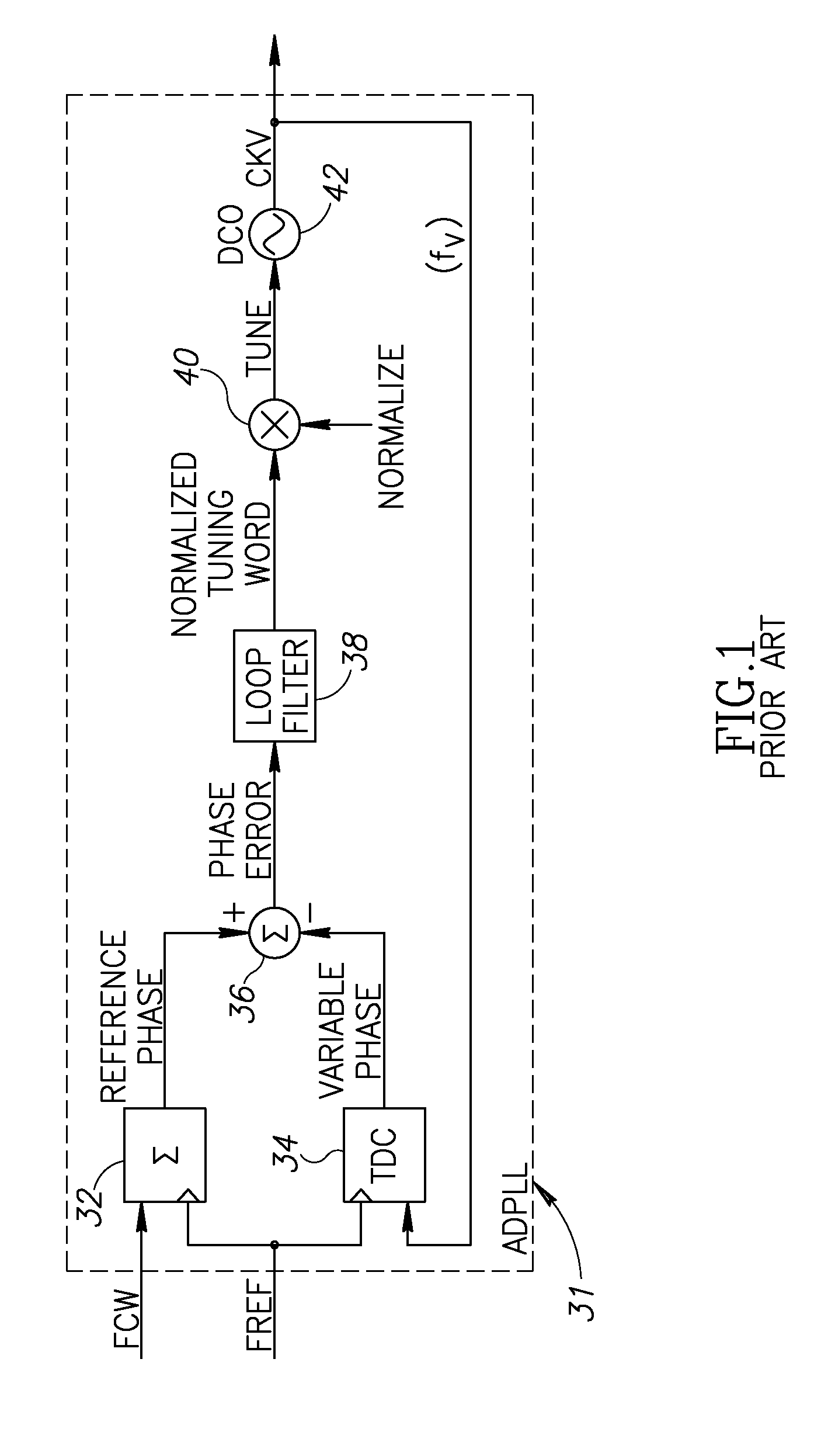
TermDefinitionASICApplication Specific Integrated CircuitCMOSComplementary Metal Oxide SemiconductorCPUCentral Processing UnitDCODigitally Controlled OscillatorADPLLAll Digital Phase Locked LoopDSPDigital Signal ProcessorFCWFrequency Command WordFPGAField Programmable Gate ArrayGSMGlobal System for Mobile CommunicationsHDLHardware Description LanguageIIRInfinite Impulse ResponseNTWNormalized Tuning WordPLLPhase Locked LoopPVTProcess, Voltage, TemperatureRFRadio FrequencyRMSRoot Mean SquaredTDCTime to Digital ConverterVCOVoltage Controlled OscillatorWCDMAWideband Code Division Multiple AccessZPRZero Phase Restart

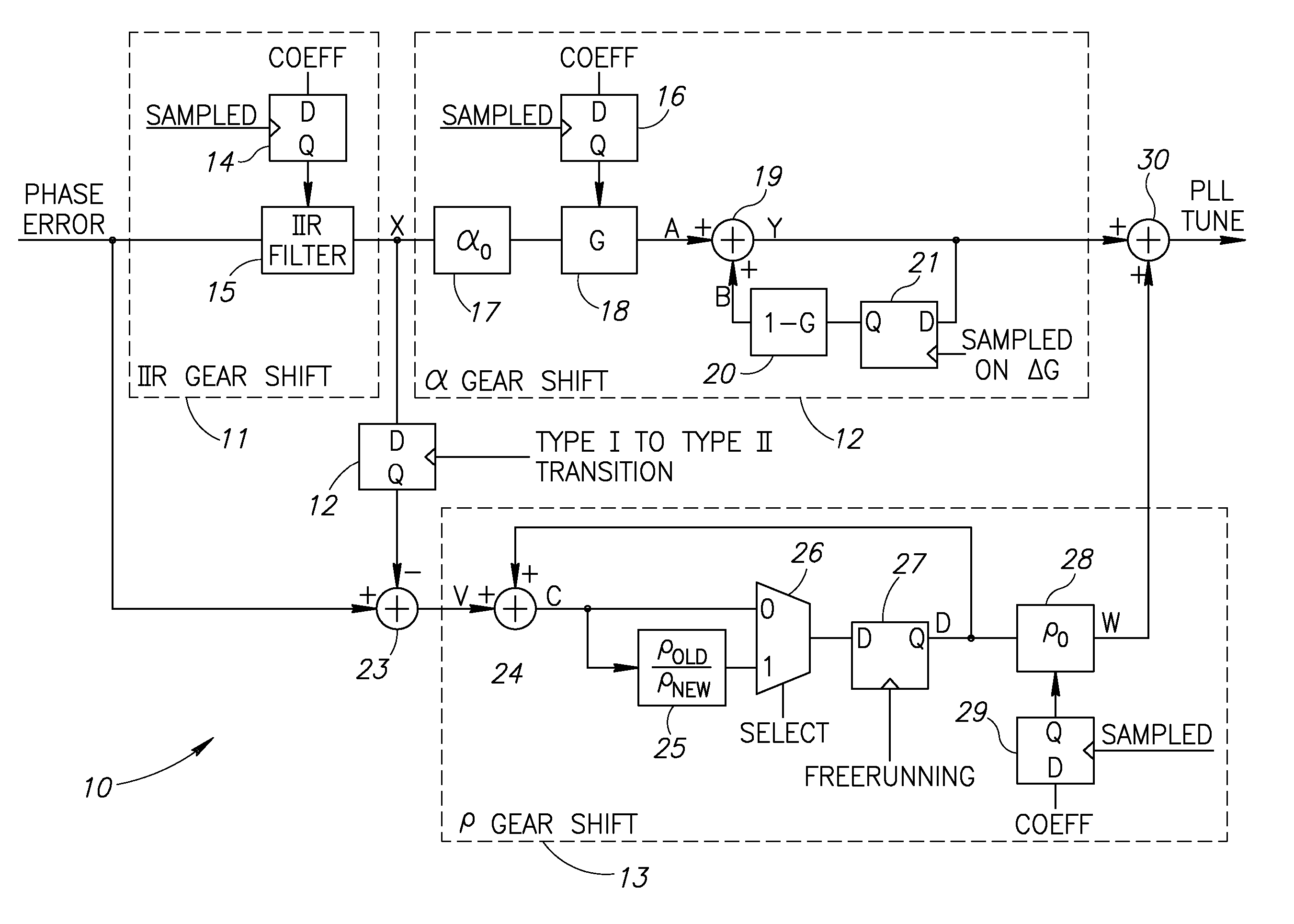
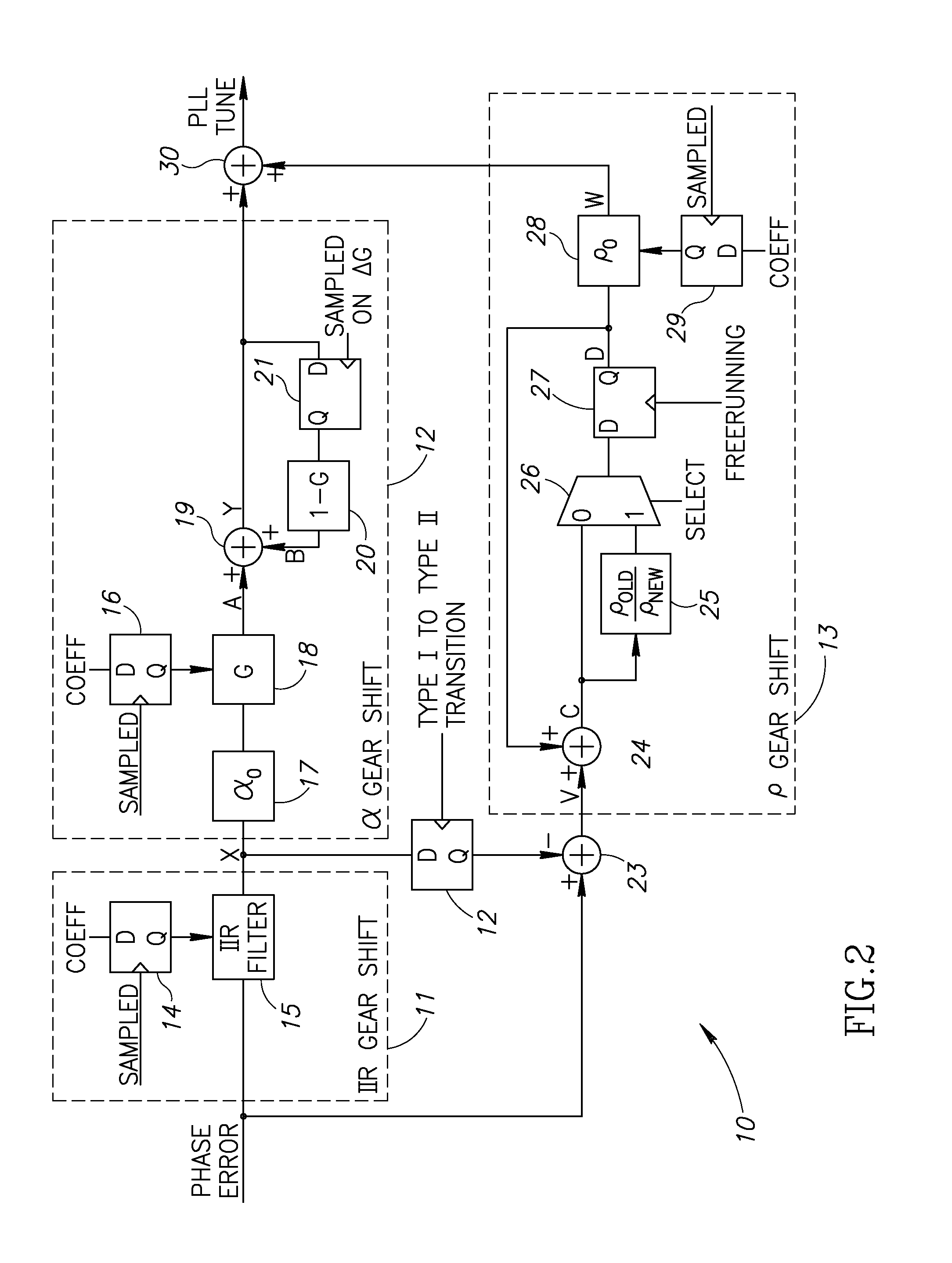
Gear Shifting Mechanism

[0031] The present invention is a gear shifting mechanism that is operative to adjust the loop gain or bandwidth of a phase locked loop (PLL) circuit at any time the PLL is operational. The mechanism is adapted for use in the loop filter circuit of a PLL loop and ...


PUM


Abstract

A novel gear shifting mechanism operative to adjust the loop gain of a phase locked loop (PLL) circuit in a continuous and reversible manner. The loop gain can be increased to widen the bandwidth of the loop and can also be decreased to narrow the loop bandwidth. The mechanism incorporates an α gear shift circuit, a p gear shift circuit and an optional IIR gear shift circuit. The α gear shift circuit comprises a infinite impulse response (IIR) filtering which enables hitless operation of the PLL loop at the occurrence of gear shift events. The α gear shift circuit comprises an accumulator whose output is multiplied by the gain value ρ. The invention enables multiple gear shifts in either positive or negative direction to be achieved by configuring the loop gain variables α and ρ which may be accomplished in software.

Description

REFERENCE TO PRIORITY APPLICATION [0001] This application claims priority under 35 U.S.C. § 119(e) to U.S. Provisional Application Ser. No. 60 / 728,274, filed Oct. 19, 2005, entitled “Continuous Reversible Gear-Shifting Based on IIR Filtering Recursive Operation,” incorporated herein by reference in its entirety.FIELD OF THE INVENTION [0002] The present invention relates to the field of communications and more particularly relates to a continuous reversible gear shift mechanism utilizing infinite impulse response (IIR)-like filtering for use in the loop filters of phase locked loops (PLLs). BACKGROUND OF THE INVENTION [0003] In modem digital radio design, the RF frequency synthesizer is a key block used for both up-conversion and down-conversion of radio signals. Traditionally, it has been based on a charge-pump PLL which is not easily amenable to scaled CMOS integration and suffers from high level of reference spurs generated by the correlative phase detection method. Use of a digit...

Claims


Application Information

Patent Timeline
Patent Type & Authority Applications(United States)
IPC IPC(8): H03B5/12
CPCH03L7/093H03L7/0991H03L7/107H03L7/1075H03L7/1806
Inventor WALLBERG, JOHNSTASZEWSKI, ROBERT B.
Owner TEXAS INSTR INC
Why Eureka
Try Eureka