Conjugated polymer fiber, preparation and use thereof
a polymer fiber and conjugated technology, applied in the field of conjugated polymer fiber, preparation and use thereof, can solve the problems of limiting the processing ability of polymer fibers, difficult nanostructure processing, modification or loss of original fiber morphology,
- Summary
- Abstract
- Description
- Claims
- Application Information
AI Technical Summary
Problems solved by technology
Method used
Image

Examples
example 1
Example 1a.
[0130] Preparation of ICP Precursor:
[0131] The ICP precursor 3 was prepared by random copolymerization of monomers 1 ((bicyclo[2.2.1]hept-5-en-2-yl)methyl acetate) and 2 ((bicyclo[2.2.1]hept-5-en-2-yl)methyl 2-(2,5-di(thiophen-3-yl)thiophen-3-yl)acetate) in an equal molar ratio via ring opening metathesis polymerization (ROMP) using Grubbs' catalyst (n =0.5). Two millimole (mmol) of monomer 1 and 2 mmol of monomer 2 were dissolved in 10 ml of dry methylene chloride and transferred via cannular into a 100 ml Schlenk flask, previously vacuum dried and nitrogen purged, under nitrogen containing 11 mg (0.013 mmol) of Grubb's alkylidene catalyst and 5 ml of methylene chloride. The mixture was allowed to stir for 30 minutes followed by the irreversible termination by the addition of 3 ml of ethyl vinyl ether. The solution was then concentrated under vacuum. The polymer 3 was precipitated 3 times in pentane (300 ml), filtered and then dried under vacuum. The number average mo...
example 1b
Electrospinning ICP Precursor 3 to Form ICP Precursor Fibers:
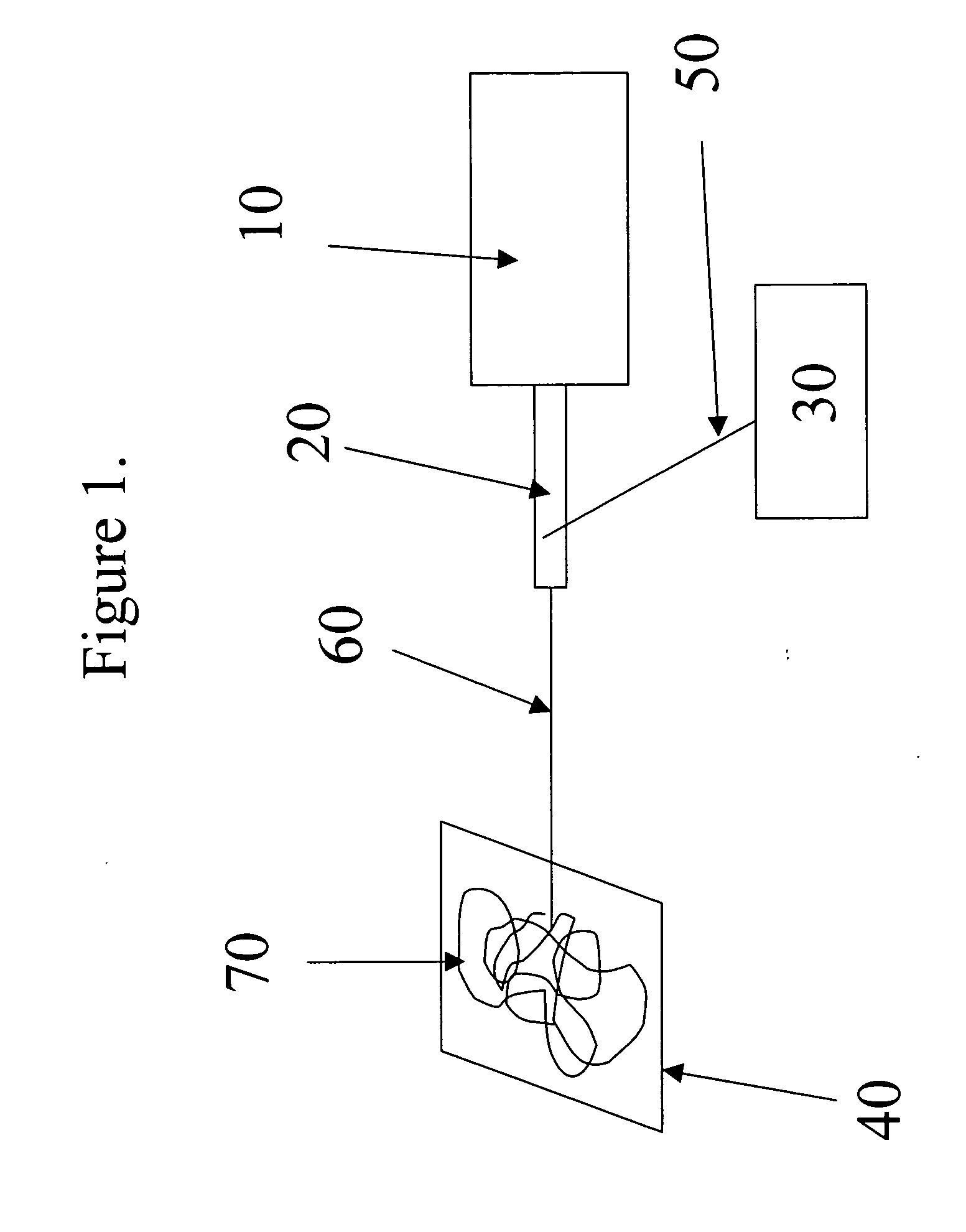
[0133] A custom electrospinning apparatus employed a Genie syringe pump (Kent Scientific) operated at a constant volumetric flow rate of 0.04 ml / h. A needle having an inner diameter of 250 micrometers was oriented downward, facing a circular collector (20 cm in diameter) separated 10 cm from the needle tip. The needle tip was positively electrified, nominally 12 kV, through a strain-relieved connection, while the collector was at ground. The tip electrical potential was controlled by a current-limited 30 kV programmable power supply (Ultravolt, Inc.) that was commanded to ramp linearly to the electrospinning voltage by a Labview program and D / A converter. The actual voltage was adjusted to ca. 12 kV in order to balance the electrically-driven flow rate with the delivered volumetric flow rate of the pump.
[0134] The ICP precursor 3 was prepared into fibers by electrospinning a 7 wt % solution of 3 in THF / DMF (70 / 30) while...
example 1c
Formation of Conjugated Fibers From ICP Precursor 3 Via Chemical Solid-state Oxidative Crosslinking:
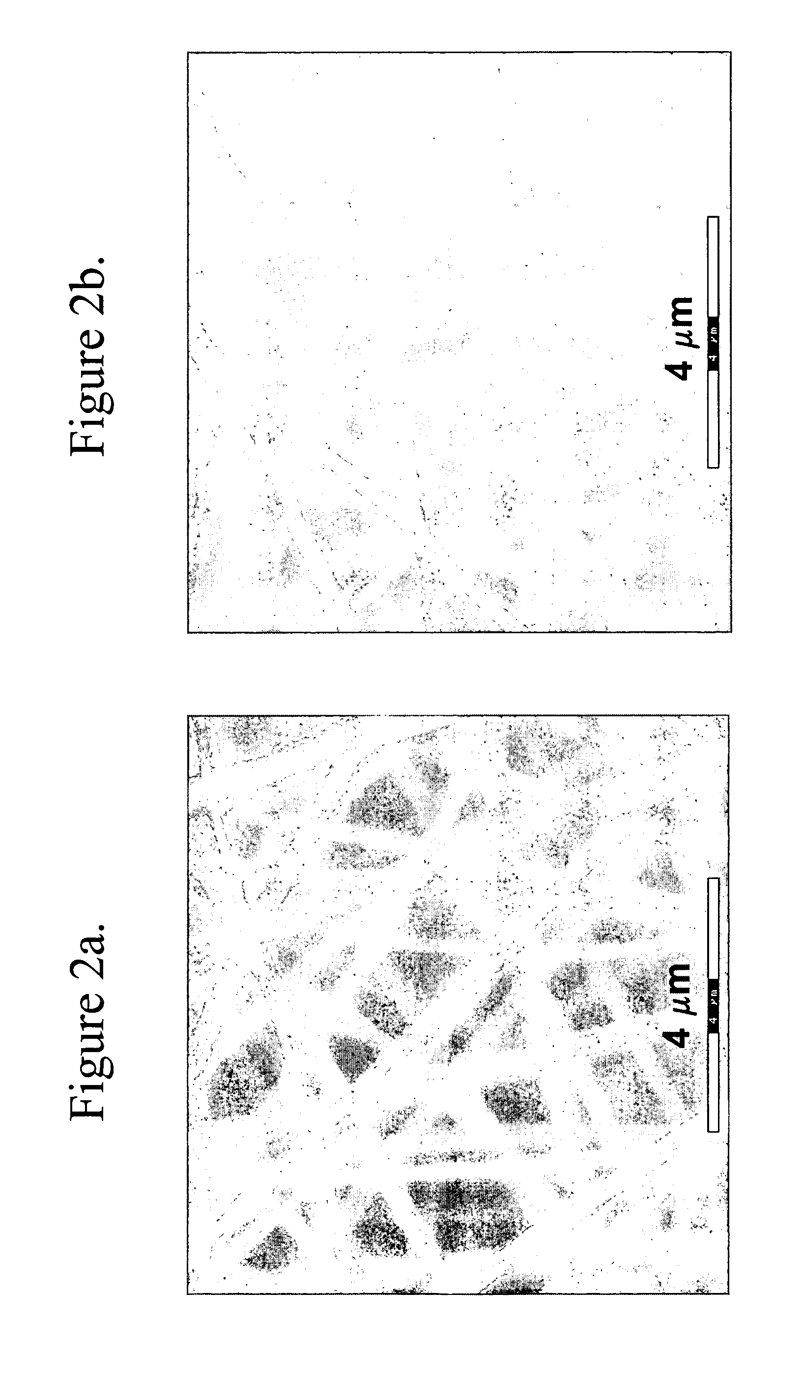
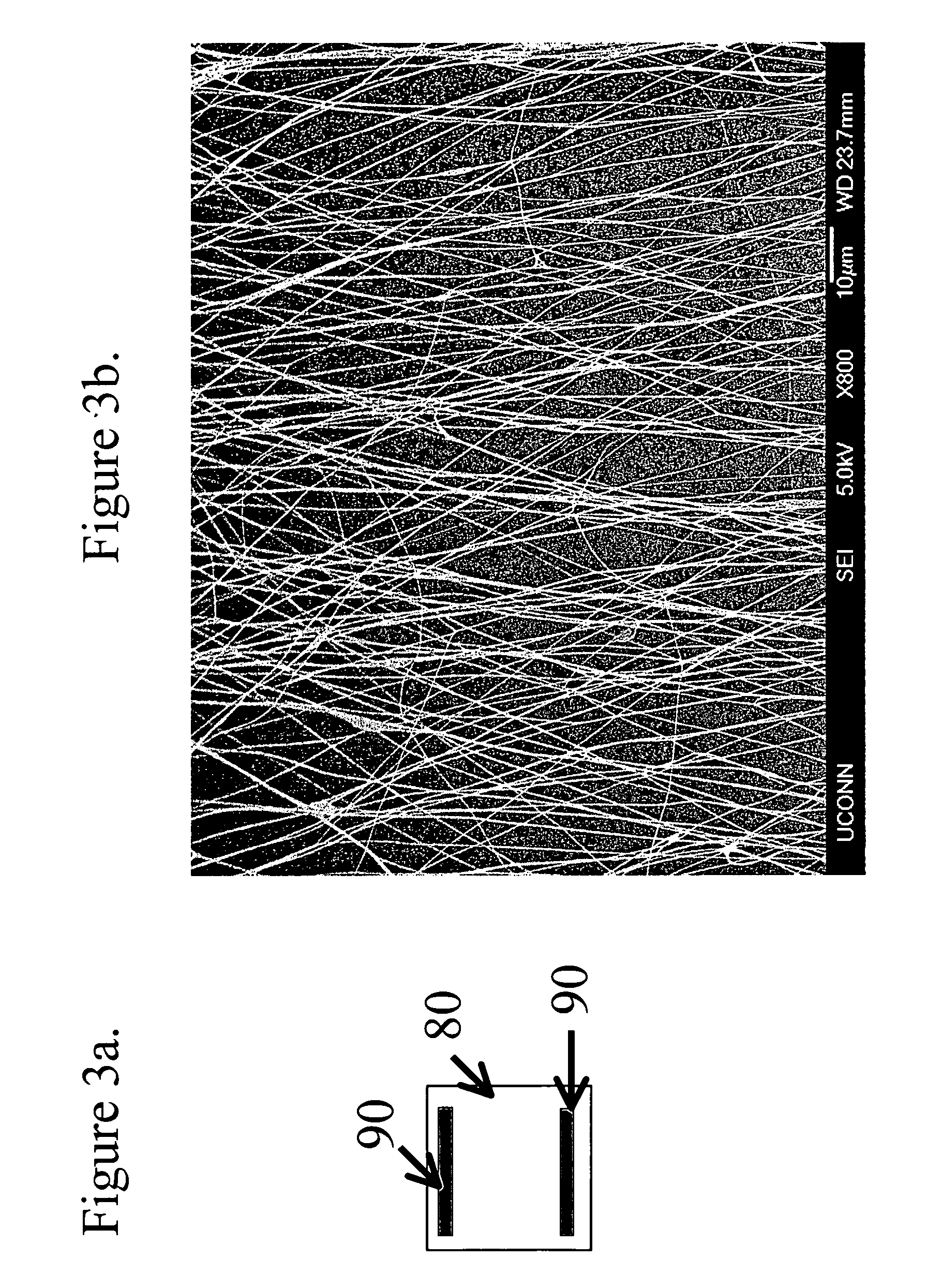
[0138] Intrinsically conductive polymer fibers were prepared by chemical oxidation by dipping the fiber mat of ICP precursor 3 into 0.01 ferric chloride / acetonitrile solution (FeCl3 / CH3CN). In a few minutes, the color of the mat changed from opaque white to deep blue indicating a successful chemical solid-state oxidative crosslinking of fibers. According to SEM images, there were no significant changes in the morphology or diameter of the fibers after the chemical solid-state oxidative crosslinking reaction.
[0139]FIG. 2b is a field emission scanning electron microscope image of crosslinked fibers after chemical solid-state oxidative crosslinking.
PUM
| Property | Measurement | Unit |
|---|---|---|
| voltage | aaaaa | aaaaa |
| voltage | aaaaa | aaaaa |
| diameter | aaaaa | aaaaa |
Abstract
Description
Claims
Application Information
 - R&D
- Intellectual Property
- Life Sciences
- Materials
- Tech Scout
- Unparalleled Data Quality
- Higher Quality Content
- 60% Fewer Hallucinations
Browse by: Latest US Patents, China's latest patents, Technical Efficacy Thesaurus, Application Domain, Technology Topic, Popular Technical Reports.
© 2025 PatSnap. All rights reserved.Legal|Privacy policy|Modern Slavery Act Transparency Statement|Sitemap|About US| Contact US: help@patsnap.com