Detection with evanescent wave probe

a technology of evanescent wave and probe, which is applied in the direction of instruments, nuclear magnetic resonance analysis, reradiation, etc., can solve the problems of large background noise, limited intrinsic sensitivity, and inability to achieve real-time detection level, so as to achieve high sensitivity and boost signal

Inactive Publication Date: 2007-04-26
INTEMATIX
View PDF36 Cites 53 Cited by
  • Summary
  • Abstract
  • Description
  • Claims
  • Application Information

AI Technical Summary

Benefits of technology

[0010] In one exemplary embodiment, an evanescent microwave orthogonal resonator probe is designed to achieve high spatial resolution and high sensitivity spin resonance detection. The probe design uses a bimodal transmission-type (or waveguide / cavity type) resonator with input and output coupled to orthogonal modes. The purpose of the design is to isolate excitation and detection modes and dramatically reduce background signal. This will allow low noise amplification to be implemented to achieve Johnson noise limited sensitivity without amplifier saturation. Only a very small spin resonance induced signal power is coupled to the probe output and amplified. Spin resonance signal is proportional to excitation RF or microwave field intensity (Hrf)2 below saturation threshold. In conventional spin resonance studies, very high power (klystron source) is required to reach the saturation level. In this design, only very small microwave power is needed to excite small volume of sample near the tip (or aperture) with very high field intensity. This will dramatically reduce the background noise of microwave source because a low noise level generator can be used. Because both excitation and pickup volume are small, other extrinsic noises will also be dramatically reduced. A typical klystron source has FM noise around −30 dB while a high quality microwave synthesizer proposed to implement in this project has FM noise around −110 dB.
[0012] In the case of an optional internal cancellation scheme, the pick up coupling will be positioned at the node of the mode of either a transmission type or cavity type resonator, equipped with evanescent probe as described above. As the evanescent probe excites the spin resonance, the induced magnetization will change the node position in the resonator. As a consequence, the pick up coupling will detect the small signal due to this spin resonance induced effect without coupling to the large excitation background signal. Low noise amplifier can then boost the signal to achieve high sensitivity in both cases.

Problems solved by technology

Although the intrinsic sensitivity is limited by cavity Johnson noise, which is near single-spin detection, this level of detection has never been possible practically.
Primary limitations in a conventional experiment are large background noise from high power excitation signal generated by high-power klystron source (need to excite spin in bulk samples) and diode detector noise since a low noise amplifier cannot be employed before a diode detector without being saturated by high level excitation signal pick up at a detection port.
Despite enormous progress in the past decades, there are still major unresolved questions regarding molecular events associated with protein folding.
Non-uniformity of the magnetic field tends to smear out the small chemical shift and reduce, if not eliminate, the effectiveness of a NMR instrument in structure determination.
In this situation, NMR machines only have the capability of structural determination for a large volume of homogenous specimen and do not have any spatial resolution.
Consequently, conventional MRI imaging technique lacks the capability of spectroscopy and structural determination.

Method used


Image

  • Detection with evanescent wave probe
  • Detection with evanescent wave probe
  • Detection with evanescent wave probe

Examples


Embodiment Construction

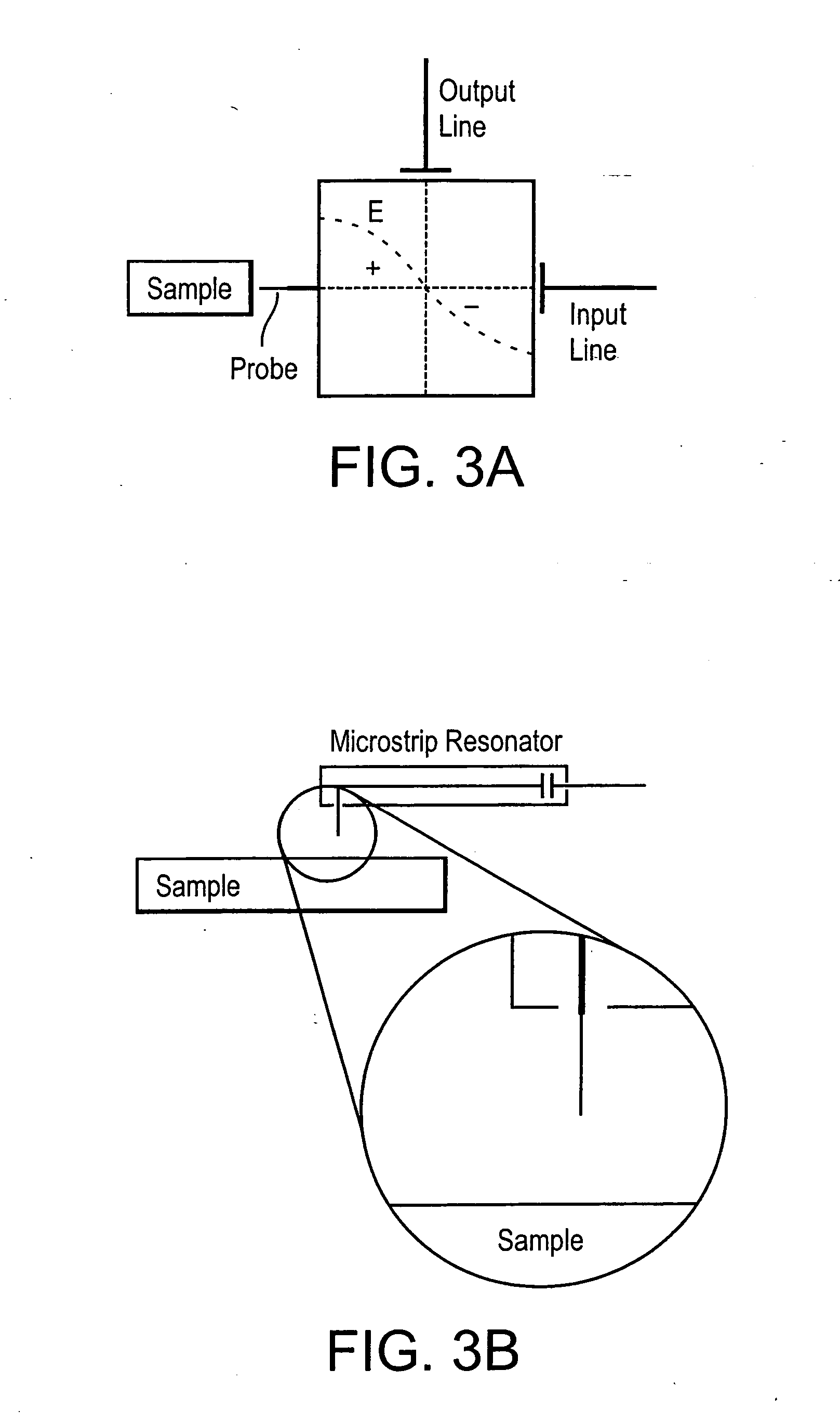
[0053] One way to improve detection sensitivity in conventional NMR is to employ a resonator with degenerate orthogonal modes. In this case, input and output channels are coupled to these orthogonal modes respectively. Ideally, the pick up coupling only picks up a signal due to spin resonance induced effects from the sample, not from the large excitation signal. Ideally, because the power fed from input channel is not coupled to the output channel, one gets a near zero-power background. The low noise amplifier can therefore be employed without being saturated. When the magnetic resonance is excited, the resonance destroys the symmetry of those orthogonal modes and couples small power to the mode that is coupled with the output channel. This small power due to the symmetry breaking is the signal power that is desired to be detected.

[0054] Witte et al. reported a design of an X-band induction spectrometer with a bimodal cavity with 110 dB isolation between transmitter and receiver [A...


PUM

PropertyMeasurementUnit
chemical shiftaaaaaaaaaa
FMR frequencyaaaaaaaaaa
volumeaaaaaaaaaa

Abstract

Methods and systems for spatially resolved spin resonance detection in a sample of material are disclosed. Also disclosed are methods and systems for spatially resolved impedance measurements in a sample of material. The disclosed methods and samples can be used in screening of plurality of biological, chemical and material samples.

Description

CROSS REFERENCE TO RELATED APPLICATIONS [0001] This application is a divisional of U.S. patent application Ser. No. 10 / 833,186, filed Apr. 28, 2004, which is a continuation-in-part of U.S. patent application Ser. No. 10 / 759,745, filed on Jan. 16, 2004, now U.S. Pat. No. 6,946,835, issues Sep. 20, 2005 which is a divisional of U.S. Pat. No. 6,693,426, filed on Feb. 9, 2002, which claims the benefit of U.S. Provisional Patent Application No. 60 / 344,427, filed on Oct. 25, 2001. This application also claims the benefit of U.S. Provisional Patent Application No. 60 / 465,736, filed on Apr. 28, 2003, and claims the benefit of U.S. Provisional Application No. 60 / 546,056, entitled “Integration of AFM / STM into Evanescent Microwave Probe” filed on Feb. 19, 2004. The entire content of each of these applications is herein incorporated by reference.FIELD OF THE INVENTION [0002] This disclosure relates to the fields of high-resolution and high-sensitivity spin resonance detection (e.g., electron sp...

Claims


Application Information

Patent Timeline
Patent Type & Authority Applications(United States)
IPC IPC(8): G01V3/00G01N24/00G01N24/10
CPCG01N24/00G01N24/006G01N24/08G01N24/10G01R33/345G01R33/60
Inventor XIANG, XIAO-DONGYANG, HAITAOWANG, GANG
Owner INTEMATIX
Why Eureka
Try Eureka