System and method for AC power generation from a reluctance machine

a technology of synchronous reluctance and control system, which is applied in the direction of electric generator control, machine/engine, dynamo-electric converter control, etc., can solve the problems of significant additional weight of the system, failure of the power generation system system or components, and loss of excitation power to the main machine, so as to reduce the size, weight and cost of the power generation system, and eliminate heat generation.

Inactive Publication Date: 2007-05-10
HONEYWELL INT INC
View PDF14 Cites 9 Cited by
  • Summary
  • Abstract
  • Description
  • Claims
  • Application Information

AI Technical Summary

Benefits of technology

[0013] In accordance with an embodiment of the present invention, a control system and method and a synchronous reluctance machine are gainfully used to achieve an AC electric power generation system as well as prime mover startup, such as for a gas engine in an aircraft. Embodiments of the present invention comprise a control system and method for providing AC power generation using a synchronous reluctance machine, and for providing AC power generation using a traditional salient-pole synchronous machine without dependence upon rotor current which is subject to failure. Embodiments of the present invention comprise a synchronous reluctance or salient-pole synchronous machine, a power converter, and associated control electronics to control AC power production of the synchronous reluctance machine or salient-pole synchronous machine. Since embodiments of the present invention operate with no field winding, the need for a PM generator, exciter machine and associated power electronics and control systems for the exciter of the traditional system is eliminated. In doing so, embodiments of the present invention can reduce the size, weight and cost of the power generation system for some applications. A higher mean time between f

Problems solved by technology

Unfortunately, several such devices may be required in order to ensure sufficient power is available in the event of total engine failure, which can incur significant additional weight to the system.
Where engine failure does not occur, of equal concern is the failure of systems or components in the power generation system.
However, the loss of excitation power to the main machine can be caused by the failure of any system or component noted above, including the armature of the PM generator, t

Method used


Image

  • System and method for AC power generation from a reluctance machine
  • System and method for AC power generation from a reluctance machine
  • System and method for AC power generation from a reluctance machine

Examples


Embodiment Construction

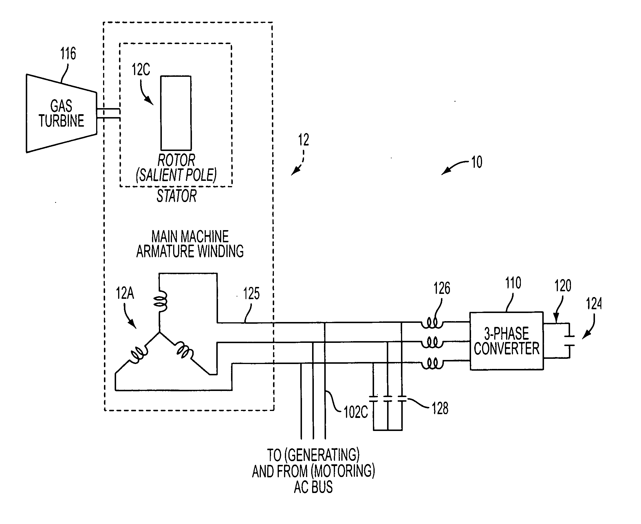
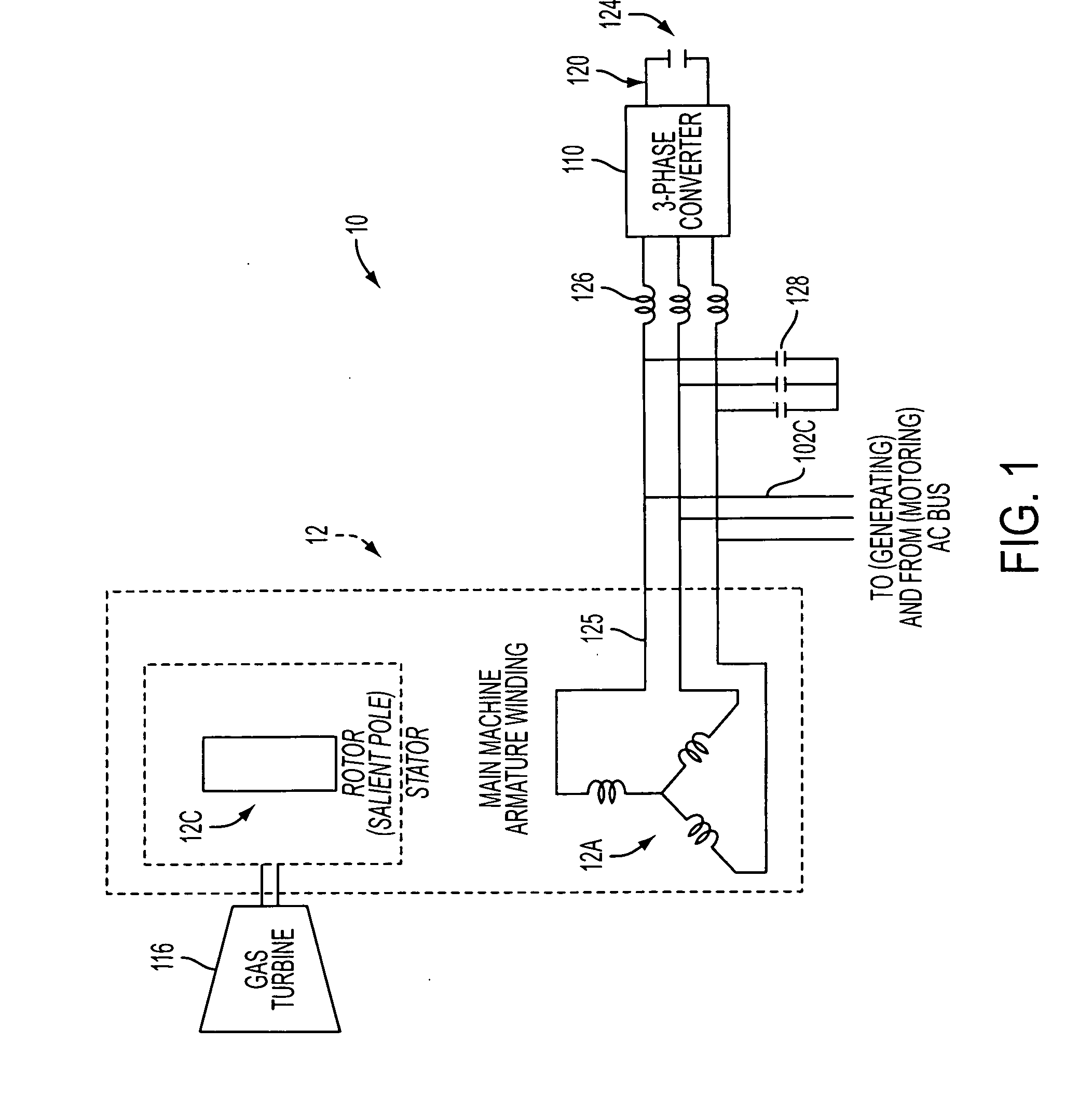
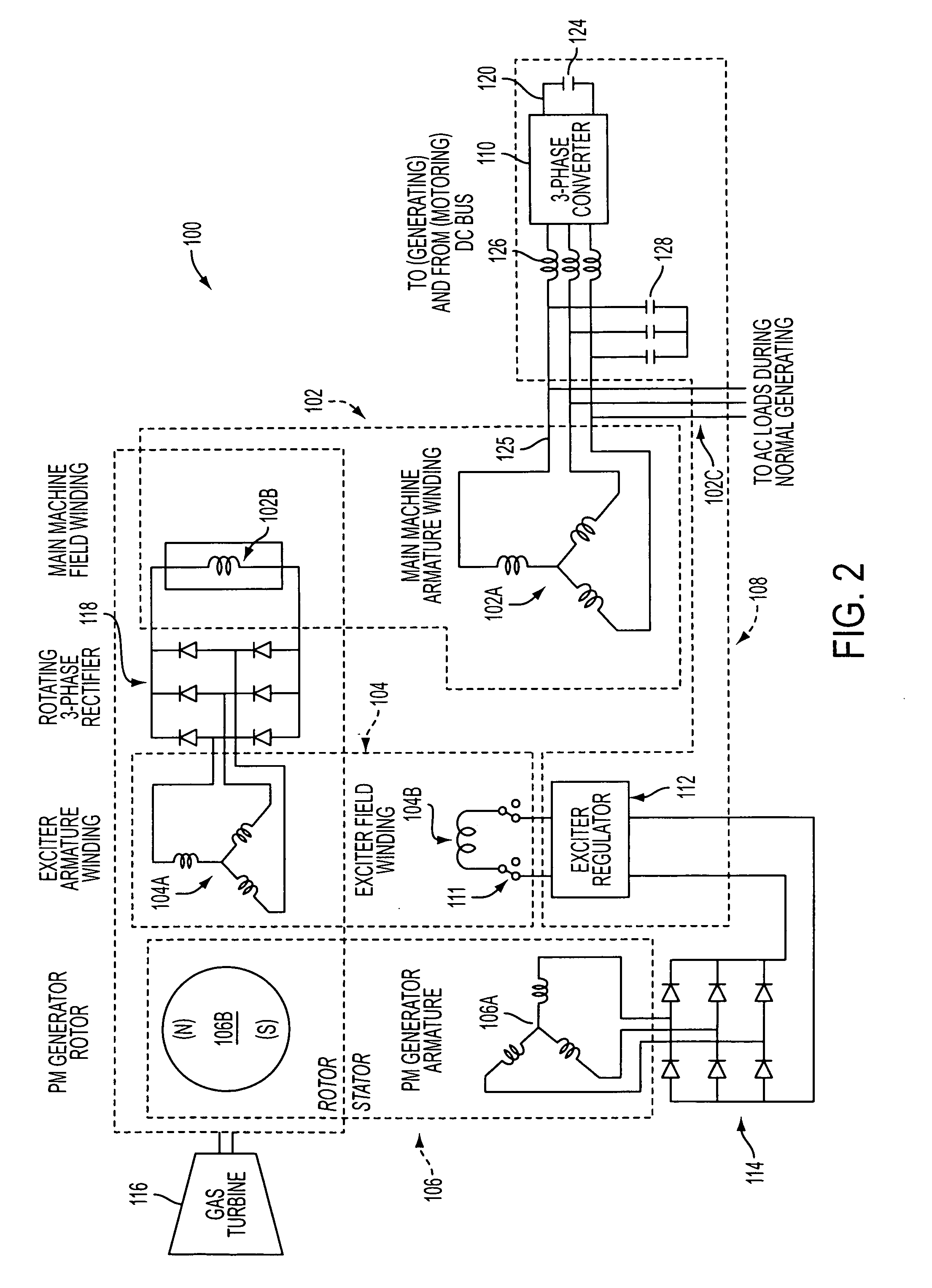
[0022] Exemplary embodiments of the present invention comprise a control system and method for achieving AC power generation using a synchronous reluctance machine or for achieving AC power generation using a traditional salient-pole synchronous machine without dependence upon rotor current which is subject to failure. Exemplary embodiments of the present invention comprise a synchronous reluctance or salient-pole synchronous machine, a power converter, and associated control electronics to control AC power production of the synchronous reluctance machine or salient-pole synchronous machine.

[0023] A synchronous reluctance machine can be defined as an electrical machine where there is no field winding or permanent magnet in its rotor, but one that has a saliency in its so called d- and q-axis reactances. The stator can be wound with three or more phase sinusoidally distributed windings. In the following exemplary implementations, embodiments of the present invention are used to achi...


PUM


Abstract

A system and method is provided for generating AC power using a synchronous reluctance machine (12) or a salient-pole synchronous machine (102) and a power converter (110). The present invention can be used to achieve power production for a synchronous reluctance machine (12), or can be used to achieve AC power from a traditional salient-pole synchronous machine/starter (102) without dependence upon a rotor current which is subject to failure. In the power generation system, the control system and method can include a power converter (110), controlled by a voltage command and at least one of a measured AC bus (125) current and voltage, and a DC link (120) voltage, for use with a synchronous reluctance machine (102) and a prime mover (116), such that movement of the rotor of the synchronous reluctance machine (102) can be used to produce at least partial AC power generation on the AC bus (125).

Description

CROSS-REFERENCE TO RELATED APPLICATIONS [0001] This application is a continuation-in-part of U.S. patent application Ser. No. 11 / 268,486, entitled “System And Method For DC Power Generation From A Reluctance Machine”, filed in the U.S. Patent and Trademark Office on Nov. 8, 2005, the entire disclosure of which is hereby incorporated by reference.FIELD OF THE INVENTION [0002] The present invention relates to a control system and method for achieving AC power generation from a synchronous reluctance machine. More specifically, the present invention relates to a control system and method to achieve AC power production from a synchronous reluctance machine or from a traditional salient-pole synchronous machine / starter without dependence upon rotor field current. BACKGROUND OF THE INVENTION [0003] Aircraft electrical power systems have increasingly required the development of systems which can provide larger and larger electrical supplies under both normal and abnormal conditions. As not...

Claims


Application Information

Patent Timeline
IPC IPC(8): H02P9/04F01D15/10H02K7/18
CPCF01D15/10H02P9/302H02P9/40H02P21/12H02P2101/30Y02T50/671F05D2220/7642F05D2220/50H02P25/08Y02T50/60
Inventor SARLIOGLU, BULENTHUGGETT, COLIN E.
Owner HONEYWELL INT INC
Why Eureka
Try Eureka