
Apparatus and method for producing carbon film using plasm cvd and carbon film

a technology of carbon film and apparatus, applied in the manufacture of electrode systems, electric discharge tubes/lamps, transportation and packaging, etc., can solve the problems of high cost of apparatus, waste of power consumption, and long time-consuming film production, and achieve low power consumption, high electron density, and efficient production

Active Publication Date: 2007-05-10
PURERON JAPAN
View PDF3 Cites 12 Cited by
  • Summary
  • Abstract
  • Description
  • Claims
  • Application Information

AI Technical Summary

Benefits of technology

The present invention is a method for producing carbon films using a plasma CVD method with a high gas pressure and a high voltage. The method requires a long time for film production and requires large and expensive apparatus. The invention proposes a new method using a cylindrical member with an opening in a vacuum chamber, through which a plasma is generated to produce a carbon film on a substrate. The voltage applied is preferably a high frequency voltage or a negative DC voltage, and the gas introduced is preferably a hydrocarbon gas. The substrate can be a long wire or a plate. The method allows for the efficient production of carbon films with a uniform thickness and at a low cost with low power consumption.

Problems solved by technology

It takes a long time for a film production.
An apparatus with a high cost is required.
Especially, an electrode area increases as compared with a film production area on a wire, resulting in a waste in power consumption.
A uniform carbon film cannot be produced all over the outer surface of a wire having a circular section.

Method used


Image

  • Apparatus and method for producing carbon film using plasm cvd and carbon film
  • Apparatus and method for producing carbon film using plasm cvd and carbon film
  • Apparatus and method for producing carbon film using plasm cvd and carbon film

Examples


Embodiment Construction

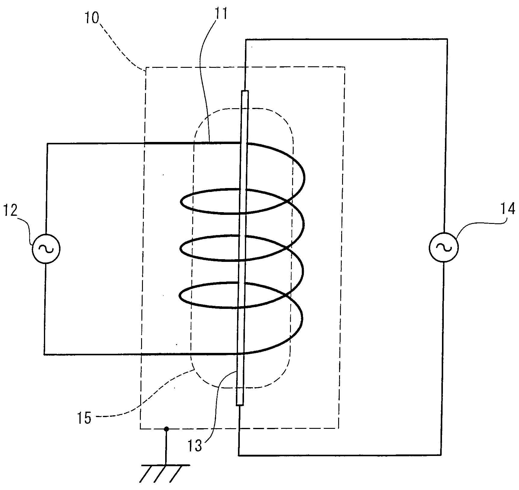
[0073] The following describes preferred embodiments of the present invention in detail with reference to the accompanying drawings.

[0074] In FIG. 1, there is shown an outline of an apparatus for producing a carbon film related to an embodiment of the present invention. In FIG. 1, a coil 11 is installed in a vacuum chamber 10 indicated with doted lines. The coil 11 is of a cylindrical member with a circumferential wall in the shape of a spiral. The cylinder 11 can be said to be a cylindrical member having an opening in part thereof. A material of the coil 11 is Cu, Ni, stainless steel, carbon or the like. A turn diameter, length and the like of the coil 11 can be selected according to a size of a substrate on which a carbon film is produced or other factors. The substrate is a conductive wire as an example. An inner space of the coil 11 is substantially in a shape of a cylinder extending in a length-wise direction of the coil 11.

[0075] A high frequency power supply 12 is connected...


PUM

PropertyMeasurementUnit
frequencyaaaaaaaaaa
frequencyaaaaaaaaaa
frequencyaaaaaaaaaa

Abstract

Provided is a method for uniformly producing a carbon film at a low cost with low power consumption. The method for producing a carbon film, including: a step of disposing a cylindrical member having an opening in part thereof in a vacuum chamber; a step of disposing a substrate inside the cylindrical member; a step of introducing a gas for carbon film production into the vacuum chamber; and a step of applying a voltage for plasma generation to the cylindrical member to thereby generate a plasma in the cylindrical member and to produce the carbon film on the surface of the substrate by the plasma.

Description

BACKGROUND OF THE INVENTION [0001] 1. Field of the Invention [0002] The present invention relates to an apparatus and a method for producing a carbon film with a nanostructure using plasma chemical vapor deposition, and a carbon film structure. [0003] 2. Description of the Related Art [0004] In a plasma chemical vapor deposition (plasma CVD) method, a carbon film can be produced on a substrate. Generally, with the plasma CVD method, a material gas is introduced while controlling a gas pressure. Application of a DC power across a pair of plate electrodes facing each other generates a plasma. A substrate is heated. By controlling ion energy directed to the substrate, a carbon film is produced on the substrate (See JP-A No. 11-50259). SUMMARY OF THE INVENTION [0005] A plasma CVD method adopts a high gas pressure. A high voltage is applied in order to generate a plasma. It takes a long time for a film production. Film production on a substrate having a large area requires plate electrod...

Claims


Application Information

Patent Timeline
Patent Type & Authority Applications(United States)
IPC IPC(8): C23C16/00
CPCC23C16/507C23C16/26H01J63/02H01J63/06Y10T428/30H01J9/025
Inventor HABA, MASANORI
Owner PURERON JAPAN
Learn More