Catalyst used to form carbon fiber, method of making the same and electron emitting device, electron source, image forming apparatus, secondary battery and body for storing hydrogen

Inactive Publication Date: 2006-07-11
CANON KK
View PDF147 Cites 27 Cited by
  • Summary
  • Abstract
  • Description
  • Claims
  • Application Information

AI Technical Summary

Benefits of technology

[0008]Generally in a conventional method of forming carbon fiber such as carbon nanotube upon a substrate by using catalytic metal with the Plasma

Problems solved by technology

Generally in a conventional method of forming carbon fiber such as carbon nanotube upon a substrate by using catalytic metal with the Plasma CV

Method used


Image

  • Catalyst used to form carbon fiber, method of making the same and electron emitting device, electron source, image forming apparatus, secondary battery and body for storing hydrogen
  • Catalyst used to form carbon fiber, method of making the same and electron emitting device, electron source, image forming apparatus, secondary battery and body for storing hydrogen
  • Catalyst used to form carbon fiber, method of making the same and electron emitting device, electron source, image forming apparatus, secondary battery and body for storing hydrogen

Examples


example 1

[0140]In the first Example, Pd and Co are added as catalyzing particles by the common sputtering manner.

[0141]Now, a method of making electron emitting device of the present example is described in detail with reference to FIGS. 1A to 1E.

(Step 1)

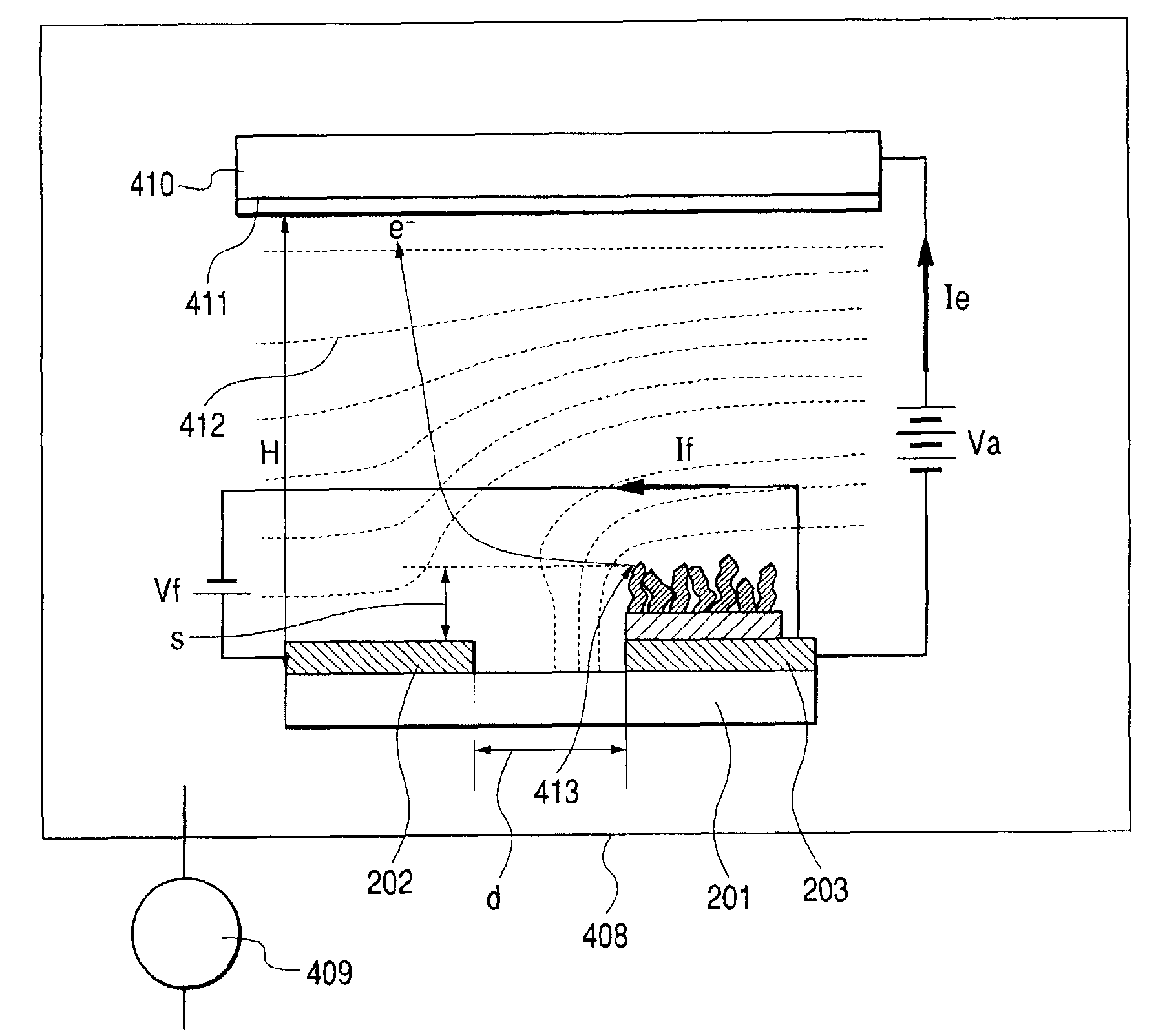
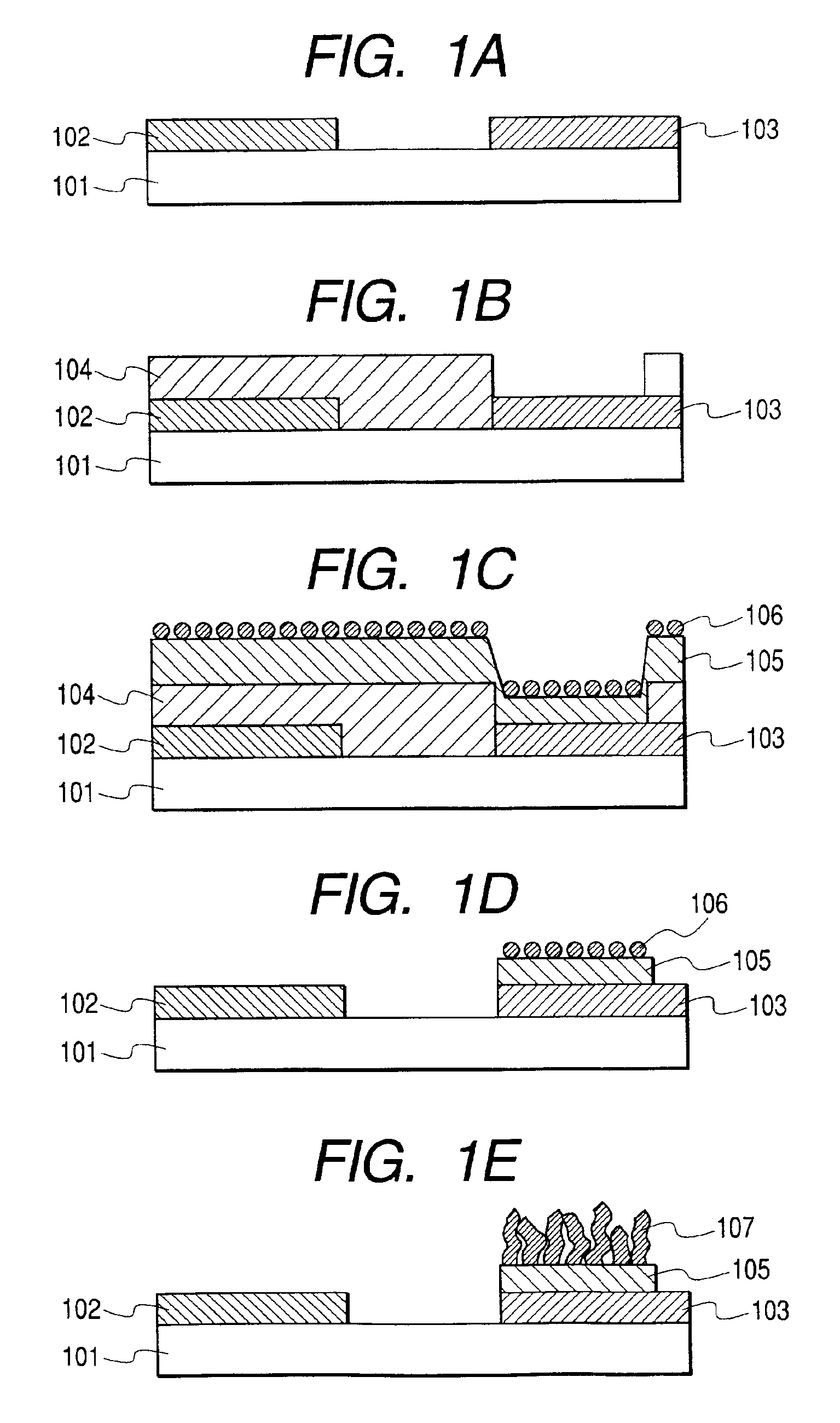
[0142]After cleaning the substrate 101 sufficiently with the quartz substrate, Ti with thickness of 5 nm and Pt with thickness of 100 nm, not shown, are continuously evaporated on overall substrate by sputtering at an initial stage in order to form the gate electrode 102 and the cathode (emitter) electrode 103.

[0143]Then, the resist pattern is formed using a not-shown positive type photoresist in the photolithography process.

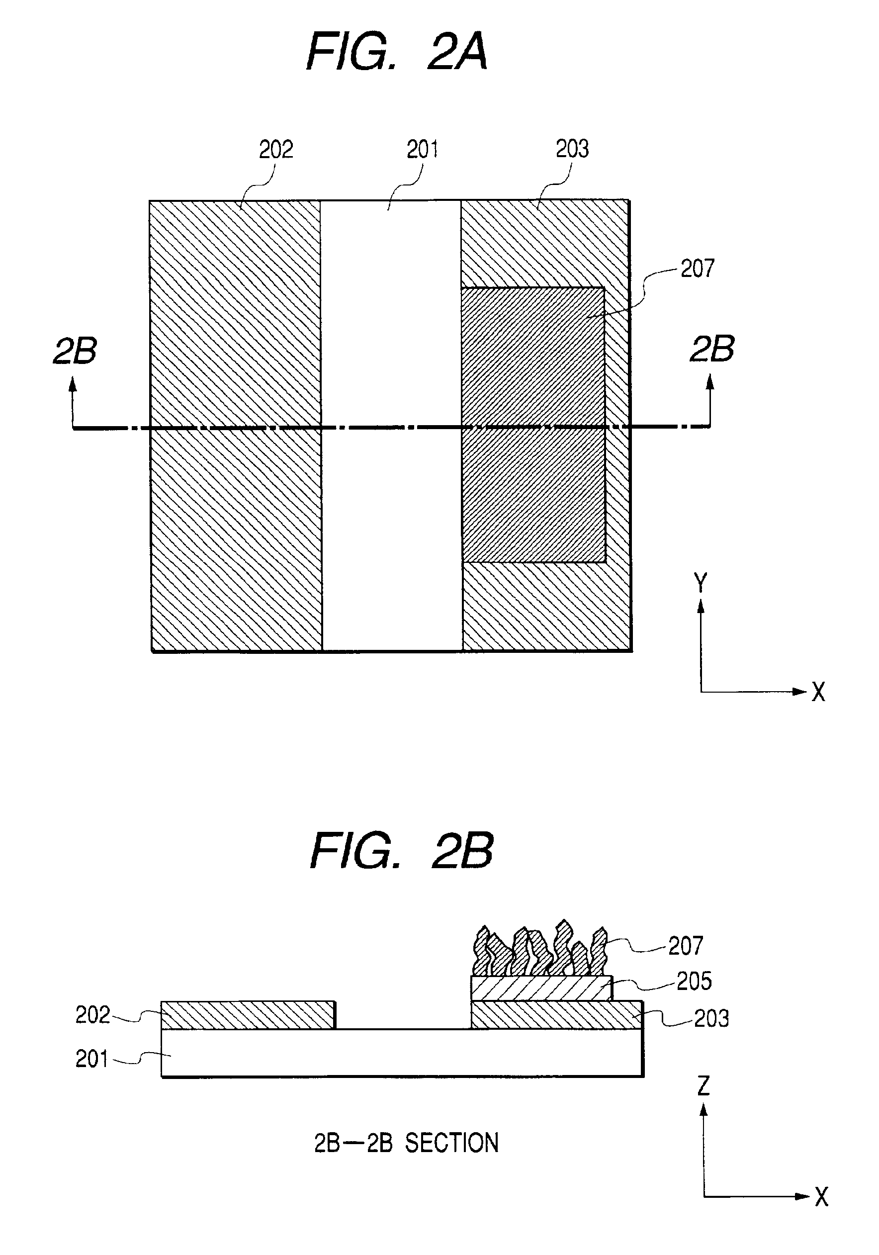
[0144]Then, the patterned photoresist as mask is dry-etched by using Ar gas on the Pt layer and Ti layer, and the gate electrode 102 and the cathode 103 having an electrode gap (width of interval) of 5 μm is patterned (FIG. 1A).

(Step 2)

[0145]The resist pattern 104 is formed using negative type photoresist used for afterw...

example 2

[0152]In the second embodiment, Pd and Fe are added as catalytic particles by common co-evaporation method.

[0153]In the present embodiment, after making the electron emitting device in a similar manner to the first embodiment, except that the second process is conducted as below, If and Ie are measured.

(Step 2)

[0154]The resist pattern 104 is formed using negative type photoresist used for lift-off of an upper layer in the photolithography process (FIG. 1B).

[0155]Then, TiN layer is formed as a conductive material layer 105 on which the carbon fiber 107 would be grown with the medium of the catalytic particles 106.

[0156]And, the catalytic particles 106 of the present invention are formed by a common electron beam (two materials simultaneously) evaporation manner as follows. Then, the catalytic particles are deposited on TiN layer by using Pd and Fe as vacuum evaporation sources. As a result, the catalytic particles 106 containing Fe component of 20 atm % to Pd is formed in an island s...

example 3

[0158]In the third embodiment, Pd and Ni are added as catalytic particles by liquid coating.

[0159]In the present embodiment, after making the electron emitting element in a similar manner to the first embodiment, except that the second process is conducted as below, If and Ie are measured.

(Step 2)

[0160]The resist pattern 104 is formed using negative type photoresist used for lift-off of an upper layer in the photolithography process (FIG. 1B).

[0161]Then, TiN layer is formed as a conductive material layer 105 on which the carbon fiber 107 would be grown with the medium of the catalytic particles 106.

[0162]And, the catalytic particles 106 of the present invention are formed by liquid coating as follows. By using mixed solution of acetic acid complex of Pd and Ni, the mixed liquid is spinner-coated. After coating, it is heated at the atmosphere. As a result, the catalytic particles 106 containing Ni component of 25 atm % to Pd is formed in an island shape (FIG. 1C).

[0163]If and Ie char...


PUM

PropertyMeasurementUnit
Diameteraaaaaaaaaa
Diameteraaaaaaaaaa
Fractionaaaaaaaaaa

Abstract

A catalyst for promoting growth of carbon fiber, which is capable of growing satisfactorily at a low temperature without needing complex process and applicable to such as electron emitting device.
The catalyst used for growth of carbon fiber contains Pd and at least one element selected in the group consisting of Fe, Co, Ni, Y, Rh, Pt, La, Ce, Pr, Nd, Gd, Tb, Dy, Ho, Er and Lu, in which 20˜80 atm % (atomic percentage) of the selected at least one element is contained to Pd.

Description

BACKGROUND OF THE INVENTION[0001]1. Field of the Invention[0002]The present invention relates to catalytic material for promoting growth of carbon and its preparing method, and electron emitting device, electron source, image forming apparatus, secondary battery and body for storing hydrogen using a carbon fiber formed by the catalytic material. The image forming apparatus of the present invention can be used as an image forming apparatus for an optical printer having a photosensitive drum as well as a display device for television broadcasting, an image display device of television conference system or computer and so on.[0003]2. Related Background Art[0004]A method of making carbon fibril is disclosed in Japanese Patent Laid-Open Gazette No. 4-504445 (corresponding family patents WO9007023 and EP0451208). Further, a method of preparing filamentary carbon is disclosed in Japanese Patent Laid-Open No. 3-260119 (corresponding family patents U.S. Pat. No. 4,900,483 and EP433507).[0005...

Claims


Application Information

Patent Timeline
IPC IPC(8): H01J9/04H01J1/30B01J23/44B01J23/63B01J23/89B01J37/02B01J37/34B82Y30/00B82Y40/00B82Y99/00C01B31/02C01B31/04C23C14/14D01F9/127H01J1/304H01J9/02H01J29/04H01J31/12
CPCB01J23/44B01J23/89B01J23/8913B01J23/892B01J35/0013B82Y10/00B82Y30/00B82Y40/00C01B31/0233D01F9/127D01F9/1273H01J9/025B01J23/63Y10S977/749B01J37/347H01J2201/30469Y10S977/724C01B32/162
Inventor KAWATE, SHINICHITSUKAMOTO, TAKEO
Owner CANON KK
Why Eureka
Try Eureka