Pulse current sensor

Active Publication Date: 2007-05-24
BARTH JON E +1
View PDF11 Cites 23 Cited by
  • Summary
  • Abstract
  • Description
  • Claims
  • Application Information

AI Technical Summary

Benefits of technology

[0025] The present invention makes use of ferrite cores to isolate both ends of the coaxial current sense resistor from its DC ground connections and to isolate the controlled impedance sensed output coaxial cable from its DC ground connection while it transports the sensed current signal to a distant location. No DC conversion of the sensed signal is required

Problems solved by technology

Microprocessor circuitry is incredibly complex and very sensitive to uncontrolled pulses of energy, such as static electric discharges (Electrostatic Discharge Voltages—“ESD”).
Additional design constraints are provided by the requirements of the expensive digitizers (similar to oscilloscopes) used to display this current and voltage data.
These conflicting requirements present problems to the prior art sensors.
However, the parasitic inductances and capacitances in the windings limit its accuracy over the time periods needed for ESD measurements.
Hall-effect sensors are both insensitive and slow—their fastest response time of slightly faster than one microsecond renders them unable to be used for faster pulse current measurements.
Additionally, the split ring ferrite core distorts the current flowing inside the coaxial transmission line, making a meaningful measurement all the more difficult.
However, inherent inductive and capacitive parasitics in the windings result in an objectionable broad band resonance at the end of the pulse, which seriously limits the measurements fidelity of long pulses.
The non-constant impedance and torturous current flow path of the Wilhelm '440 sensor could not provide sub-nanosecond rise time measurement capabilities.
After the sensed signal is coupled to the measuring circuit, the measured signal must be integrated t

Method used


Image

  • Pulse current sensor
  • Pulse current sensor
  • Pulse current sensor

Examples


Embodiment Construction

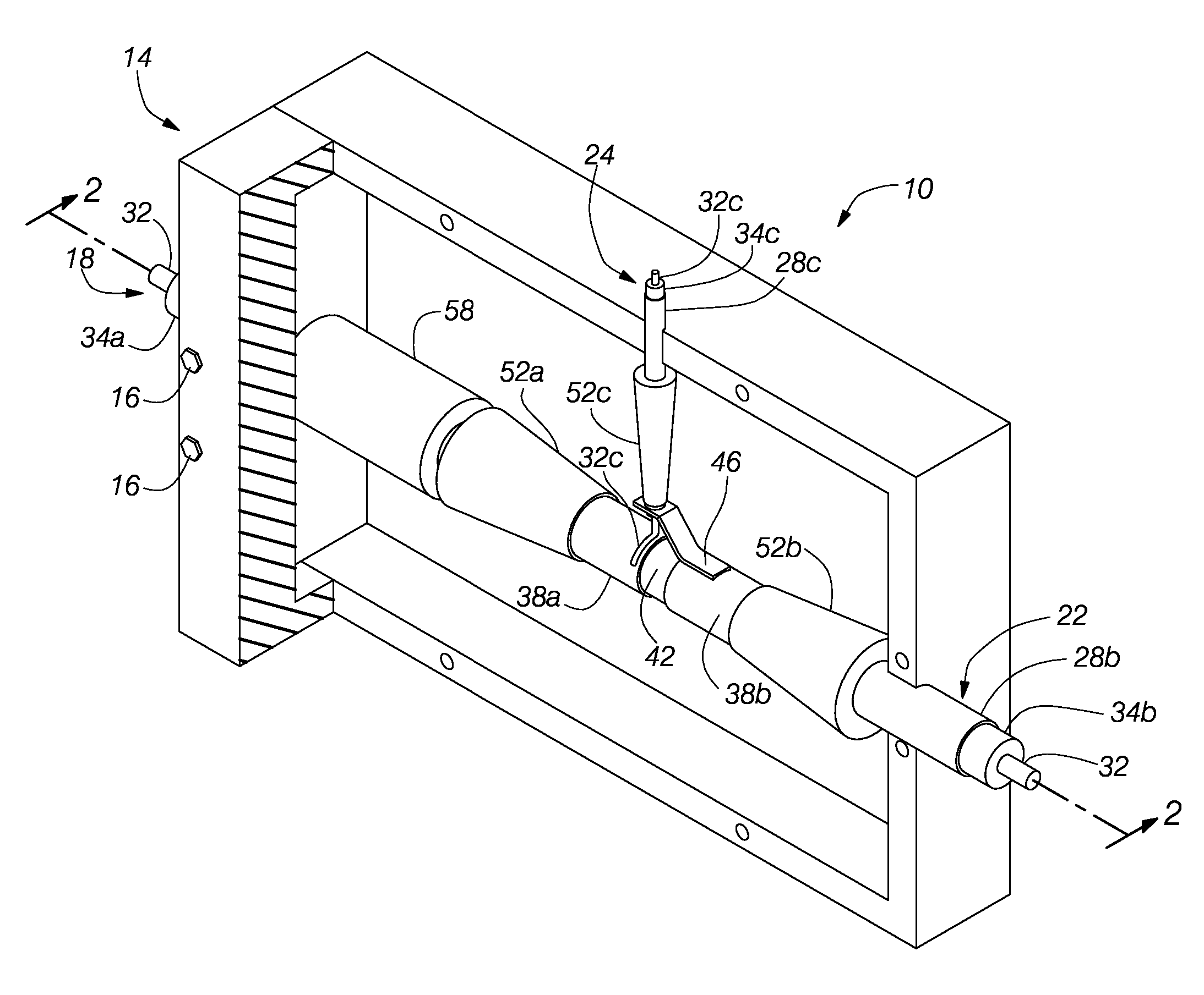
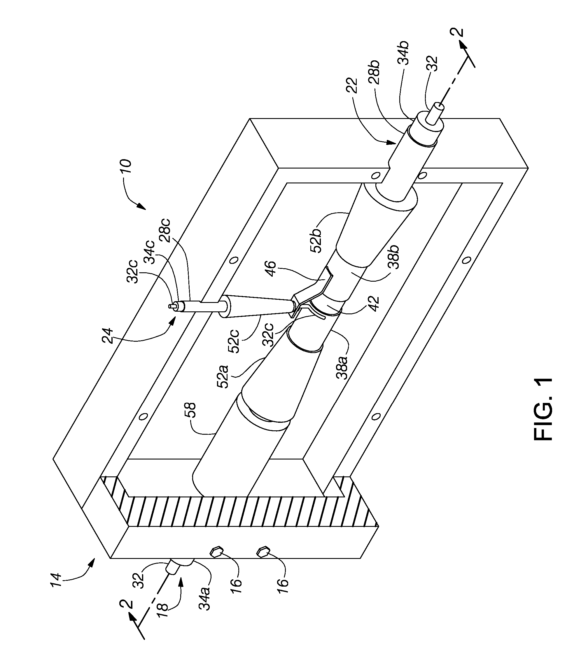
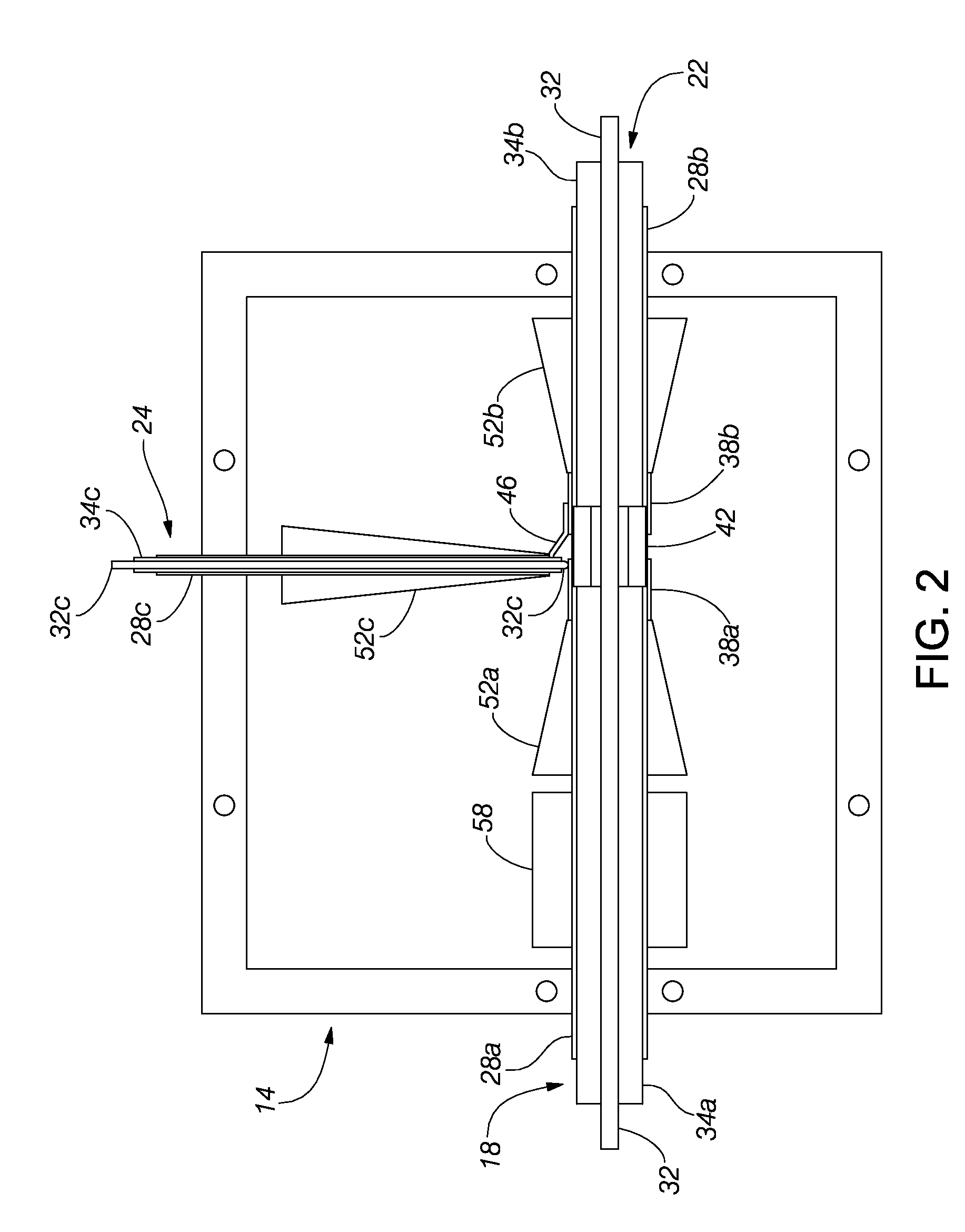
[0037] The following description and the accompanying drawings illustrate exemplary embodiments of a pulse coaxial current sensor. The description and drawings are intended to be illustrative of the inventions defined in the appended claims. In the drawings, like numerals refer to like parts throughout.

[0038] In FIG. 1, a pulse coaxial current sensor 10 utilizes an outer shield box 14 comprising a low-resistance metal, which is electrically and mechanically connected to an entrance coaxial conductor 18, an exit coaxial conductor 22, and a current sensor output (e.g., extraction) coaxial conductor 24. In a preferred embodiment, the metal shield box 14 comprises matched halves that are removable attached together utilizing a plurality of fasteners 16.

[0039] The entrance coaxial conductor 18 comprises an outer conductor 28a and an inner conductor 32. The outer conductor 28a and the inner conductor 32 are separated by an inner insulator 34a. The exit coaxial conductor 22 comprises an ...


PUM


Abstract

A sensor measures the current in high frequency pulses (e.g., pulses having fast rise times) that are transported on coaxial transmission lines. The sensor includes an entrance coaxial conductor and an exit coaxial conductor that are interconnected by a continuous inner conductor. The outer conductors of the two coaxial conductors are interrupted and are interconnected by a sensing resistor with a substantially constant resistance. An output sensor coaxial conductor has an inner conductor electrically connected to a first end of the sensing resistor and has an outer conductor connected to a second end of the sensing resistor. Tapered ferrite cores are placed around the three coaxial conductors proximate the connections to the sensing resistor. Preferably, the sensing resistor is a tubular resistor formed on a dielectric cylindrical tube. The sensor is enclosed within a continuous conductive housing.

Description

RELATED APPLICATIONS [0001] The present application claims the benefit of priority under 35 U.S.C. § 119(e) to U.S. Provisional Application No. 60 / 596,131, filed on Sept. 1, 2005.BACKGROUND OF THE INVENTION [0002] 1. Field of the Invention [0003] The present invention is in the field of measurement of currents produced by pulses having fast rise times. [0004] 2. Description of the Related Art [0005] Fast-pulsed power measurements and sensors to make these measurements were needed in the atomic age, where researchers needed to monitor fast high voltage signals produced by Compton diode radiation sensors located close to nuclear explosions. The Compton diode provided voltage waveforms greater than 10,000 volts which were analyzed to determine details of the nuclear chain reaction. To “freeze” the many details of the reaction requires fast accurate voltage measurements on the order of a nanosecond or less. Much high power pulse instrumentation is largely the result of the technology de...

Claims


Application Information

Patent Timeline
IPC IPC(8): G01R27/08
CPCG01R15/146G01R19/0053G01R31/002
Inventor BARTH, JON E.RICHNER, JOHN R.
Owner BARTH JON E
Why Eureka
Try Eureka