
LED lighting assemblies with thermal overmolding

a technology of led lighting and thermal overmolding, which is applied in the field of led lighting assemblies, can solve the problems of large heat sinks, relatively inefficient heat dissipation, and substantial cost and weight of metal heat sinks in lighting assemblies, and achieve the effect of thermal conductivity

Active Publication Date: 2007-05-31
GE LIGHTING SOLUTIONS LLC
View PDF24 Cites 370 Cited by
  • Summary
  • Abstract
  • Description
  • Claims
  • Application Information

AI Technical Summary

Benefits of technology

[0010] According to one aspect, a lighting assembly is disclosed, including a printed circuit board and one or more light emitting diode diodes (LEDs) disposed on the printed circuit board and connectable with a power source via circuitry of the printed circuit board. A t...

Problems solved by technology

A metal heat sink adds substantial cost and weight to the lighting assembly, and may be relatively inefficient at dissipating heat.
Common heat sink metals such as copper have high density, making heat sinks massive.
To achieve good thermal coupling with the ambient, metal heat sinks typically include fins or other radiating structures, which increases weight and bulk of the heat sink.
However, these approaches add substantial cost, bulk, and complexity to the lighting assembly.
Another problem with metal heat sinks is that the thermal pathway from the LED to the metal heat sink is of limited area.
If the LED is mounted by mounting leads, the thermal pathway may be limited to the area of the leads.
Such underfilling, especially when used in conjunction with an LED having an integral heat slug, substantially increases the thermal pathway area, but generally cannot increase the thermal pathway area substantially beyond the overall footprint area of the LED.
The container or housing adds weight and bulk to the lighting assembly, and may be problematic for certain low-profile lighting assemblies.
Moreover, the potting material typically does not have enough thermal mass by itself to dissipate heat generated by the LEDs.

Method used


Image

  • LED lighting assemblies with thermal overmolding
  • LED lighting assemblies with thermal overmolding
  • LED lighting assemblies with thermal overmolding

Examples


Embodiment Construction

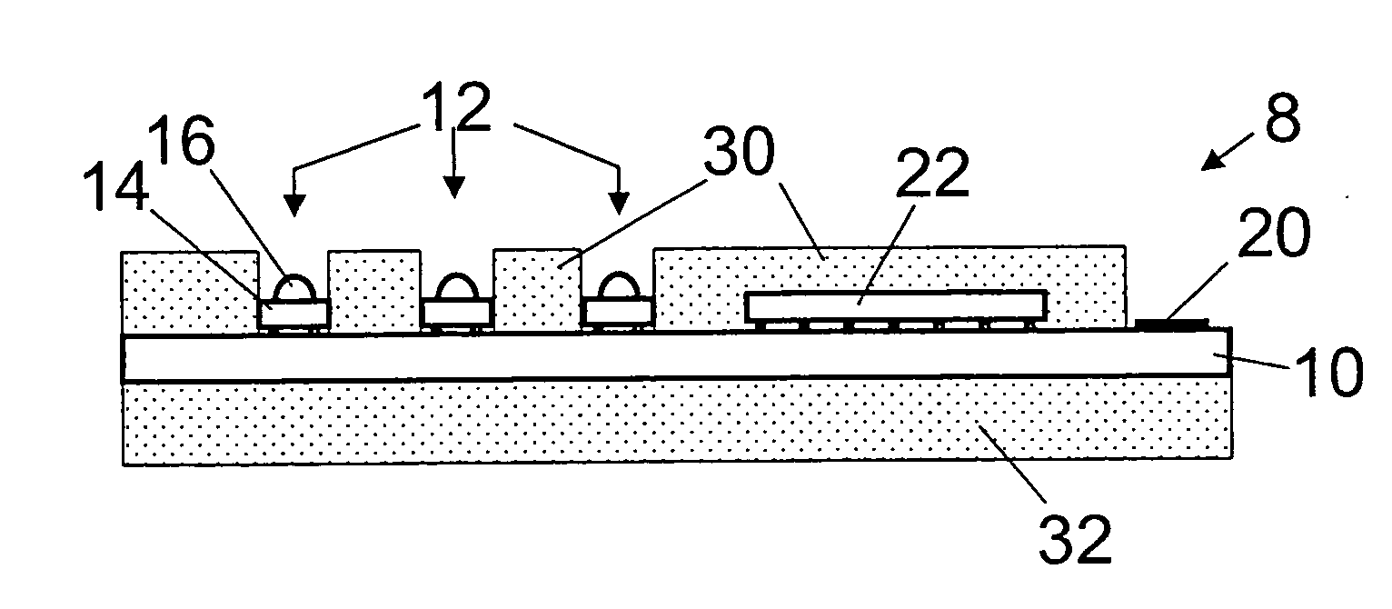
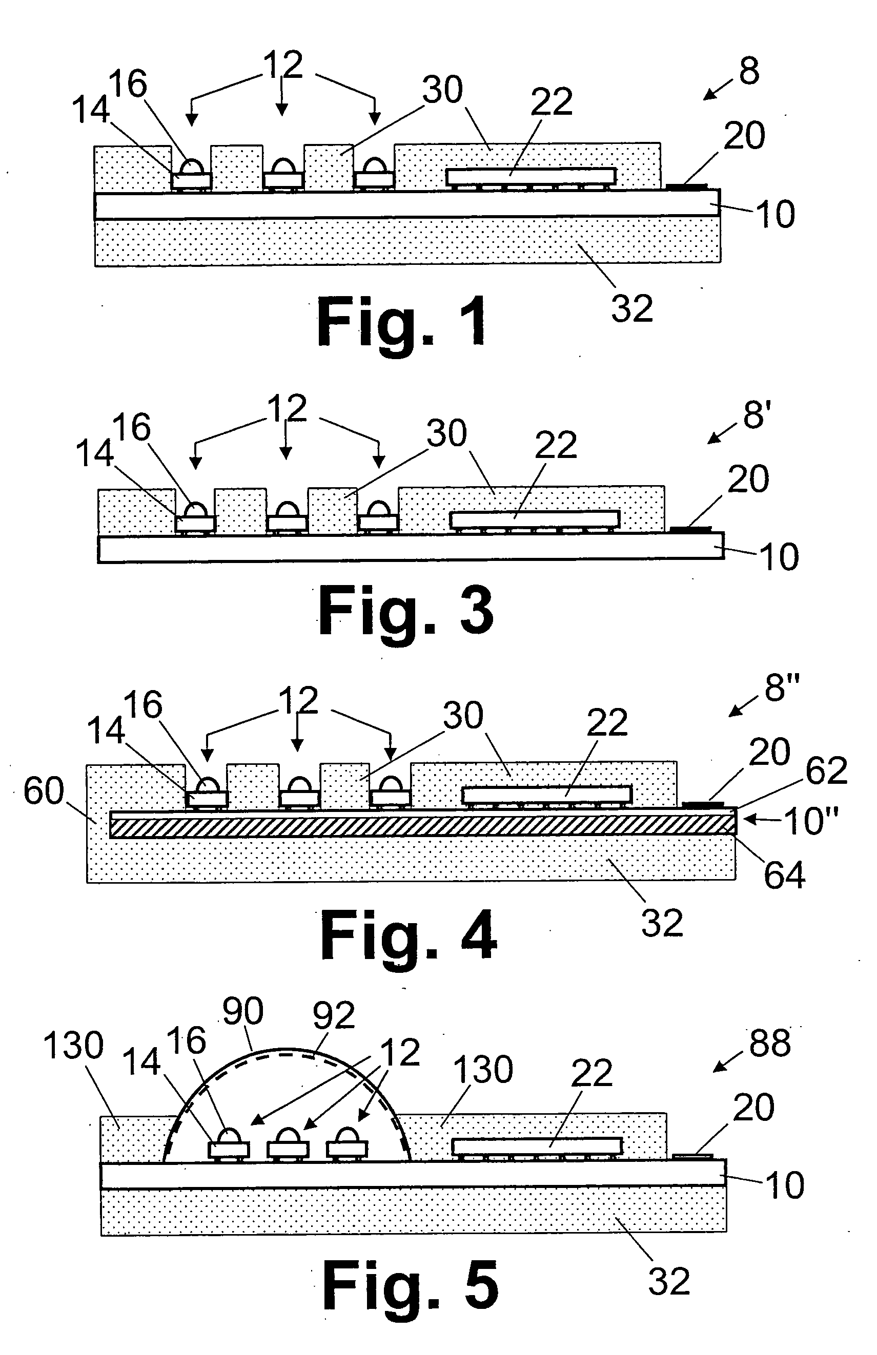
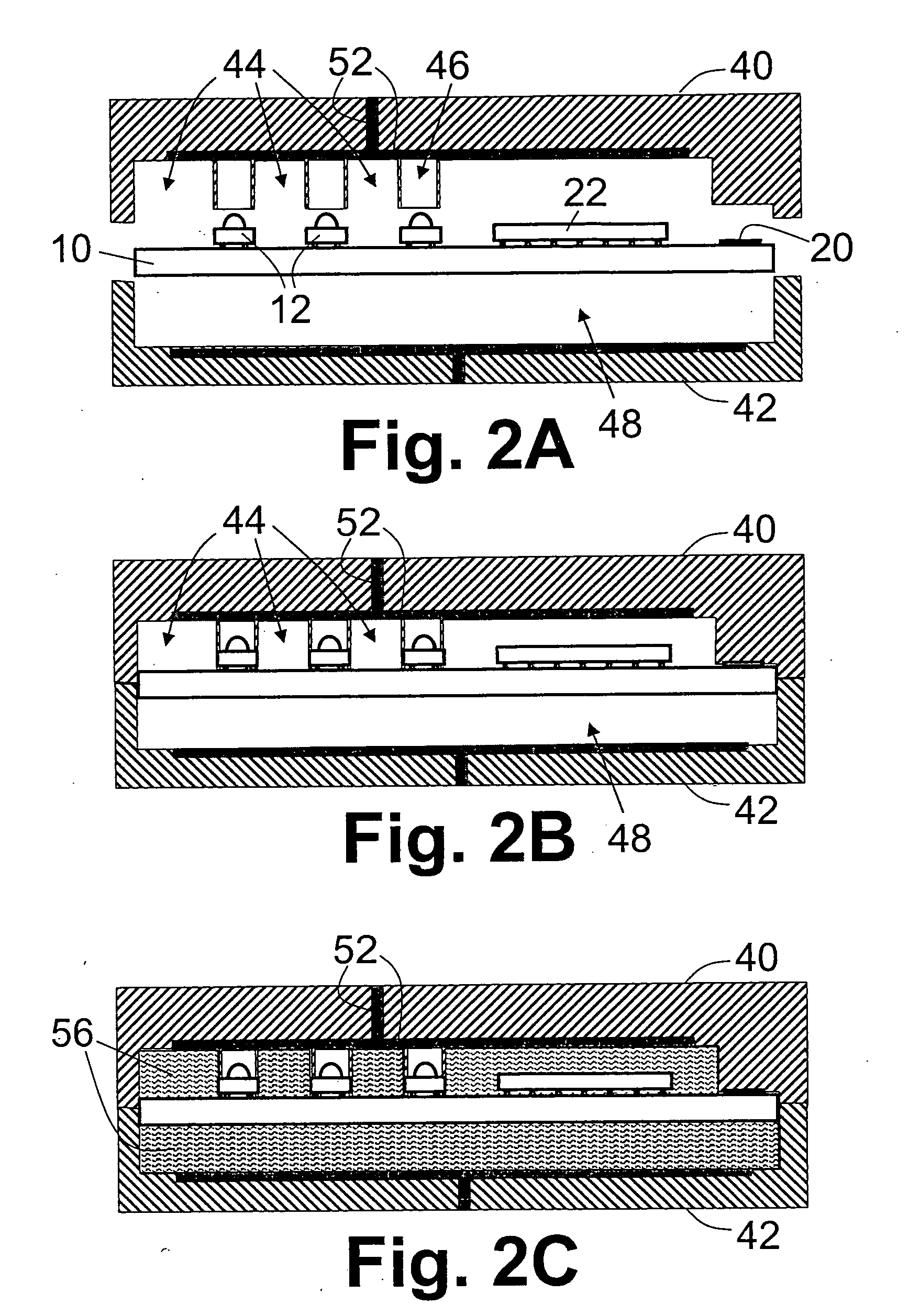
[0024] With reference to FIG. 1, a lighting assembly 8 includes a printed circuit board 10 on which one or more light emitting diodes (LEDs) 12 are attached. In the illustrated embodiment, three LEDs are attached to the printed circuit board, however, the number of attached LEDs can be one, two, three, four, or more. Substantially any type of LED can be attached, such as for example: a white LED including an ultraviolet group III-nitride-based electroluminescent semiconductor diode coated by a white-light emitting phosphor blend; a white LED including a blue or violet group III-nitride-based electroluminescent semiconductor diode coated by a yellowish-light emitting phosphor blend; a blue LED including a blue group III-nitride-based electroluminescent semiconductor diode; a red LED including a red group III-arsenide, group III-phosphide, or group III-arsenide-phosphide electroluminescent semiconductor diode; a red LED including a red group III-arsenide, group III-phosphide, or group...


PUM

PropertyMeasurementUnit
Temperatureaaaaaaaaaa
Thermal conductivityaaaaaaaaaa

Abstract

One or more light emitting diode diodes (LEDs) are attached to a printed circuit board. The attached LEDs are connectable with a power source via circuitry of the printed circuit board. An overmolding material is insert molded an over at least portions of the printed circuit board proximate to the LEDs to form a free standing high thermal conductivity material overmolding that covers at least portions of the printed circuit board proximate to the LEDs. The free standing high thermal conductivity material has a melting temperature greater than about 100° C. and has a thermal conductivity greater than or about 1 W / m·K. In some embodiments, the free standing high thermal conductivity material is a thermoplastic material.

Description

BACKGROUND [0001] The following relates to the lighting arts. It especially relates to LED-based lighting assemblies including LED-based lighting assembly modules for flexible lighting strips. However, the following will also find application in conjunction with lighting assemblies, methods for manufacturing lighting assemblies, electronics associated with lighting assemblies, and applications employing lighting assemblies, such as illumination, illuminated channel lettering, border lighting, and so forth. [0002] Light emitting diodes (LEDs) are used in lighting assemblies, where they have certain advantages of incandescent, fluorescent, and other lighting technologies. For example, LEDs are compact, durable, relatively energy efficient, operable at low voltage, and so forth. In a typical arrangement, one or more LEDs are attached to a printed circuit board and are connectable with a power source via circuitry of the printed circuit board. If the power source is not directly compati...

Claims


Application Information

Patent Timeline
IPC IPC(8): F21V29/00F21K99/00
CPCF21S4/001F21V29/85F21V29/004F21Y2101/02G09F9/33H05K1/0203H05K3/284H05K2201/0129H05K2201/0209H05K2201/10106H05K2203/1316F21V31/04F21V3/0481F21V9/16F21V23/005F21V23/007F21V23/023Y10T29/49146Y10T29/4913F21V29/70F21S4/003F21S4/10F21S4/20F21V3/12F21V9/06F21Y2101/00F21Y2115/10F21V3/10H05K1/0209F21K9/90F21V3/02F21V23/001H05K1/181H05K3/32
Inventor NALL, JEFFREYMRAKOVICH, MATTHEW
Owner GE LIGHTING SOLUTIONS LLC
Learn More