
Method for manufacturing fine composite particles, apparatus for manufacturing fine composite particles, and fine composite particles

Active Publication Date: 2007-06-07
NAT INST OF ADVANCED IND SCI & TECH
View PDF6 Cites 26 Cited by
  • Summary
  • Abstract
  • Description
  • Claims
  • Application Information

AI Technical Summary

Benefits of technology

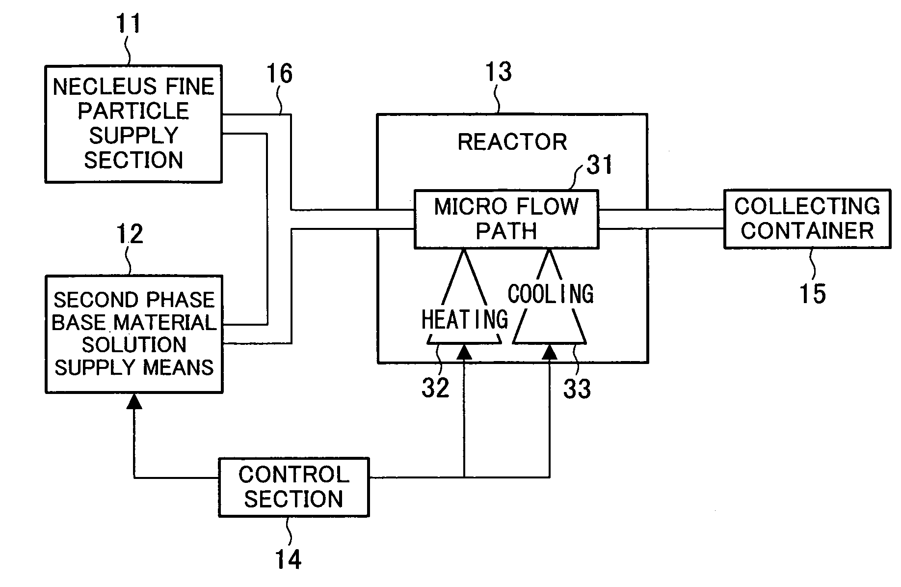
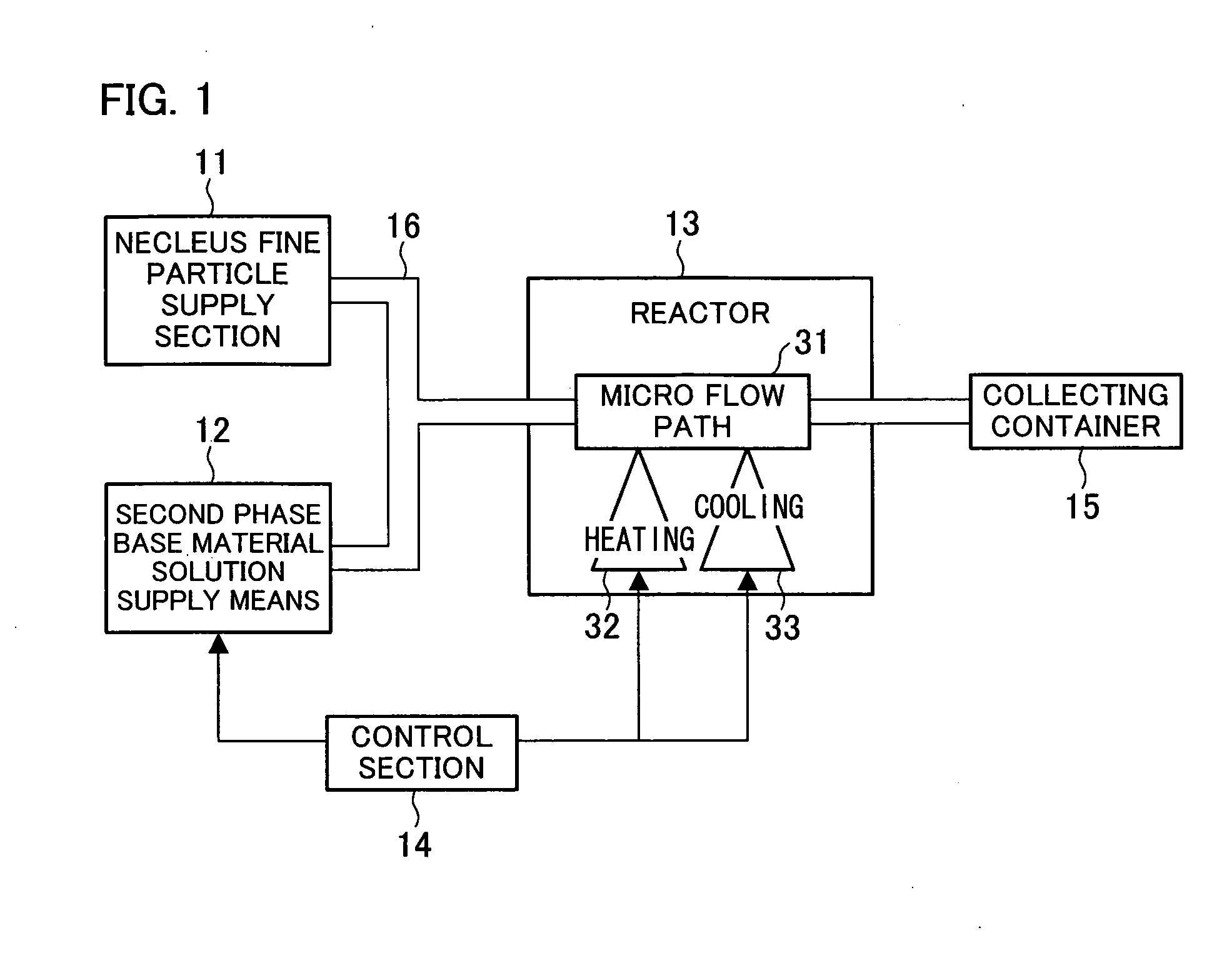
[0015] As a result of intensive studies of fine particle manufacturing methods, the inventors of the present invention has found that a method using a micro flow path allows accurate control in temperature / concentration / retention time, and therefore enables continuous production of fine composite particles, while adjusting amount of coating. With this finding, the inventors completed the present invention.
[0033] In the method and apparatus of the present invention for manufacturing fine composite particles, the micro flow path used for the fine particle composite process is set to 1-4000 in Reynolds number. With this structure, the present invention provides an advantage that the reaction condition in the composite reaction process can be accurately controlled without setting a longer reaction time, allowing mass production of coating-type nano fine composite particles, in each of which a nuclei for fine particle is coated with a layer. Further, the present invention particularly allows controls of reaction temperature and retention time, thereby ensuring continuous control of particle diameter in manufacturing fine composite particles.

Problems solved by technology

However, the method of controlling diameter of particle by changing the temperature / duration in the reaction process, the control is not easy, and also the quality of resulting particles may be not always good.
More specifically, the conventional particle-manufacturing apparatuses are not capable of accurate control of the temperature / duration in the reaction process in the manufacturing of coated composite particles.
In other words, the accurate control in the reaction conditions is indispensable to accurate control of coating amount, but it cannot be achieved by the conventional manufacturing apparatuses.
However, this sometimes requires a change in condition of the reaction system, and an excessively long reaction process causes an increase in particle size distribution due to Oswald maturation or the like.

Method used


Image

  • Method for manufacturing fine composite particles, apparatus for manufacturing fine composite particles, and fine composite particles
  • Method for manufacturing fine composite particles, apparatus for manufacturing fine composite particles, and fine composite particles
  • Method for manufacturing fine composite particles, apparatus for manufacturing fine composite particles, and fine composite particles

Examples


example 1

First Example of ZnS Coated CdSe Fine Particle Synthesizing Process

[0144] A solution (first solution containing a particle-forming precursor) prepared by adding 165 μl of octyl amine and 26.6 mg of cadmium acetate to 5 ml of octadecene was mixed by a ratio of 1:1 with another solution in which 494 μl of serene is dissolved in 25 ml of trioctyl phosphine (TPO). The mixture was supplied to a syringe pump until it filled up the pump, and then was poured into a capillary (a micro flow path of a material-synthesizing reactor), which was heated to 275° C., so that it runs through the tube. Produced was a CdSe fine particle solution (average particle diameter=3 nm), which serves as nuclei for fine particle.

[0145] A solution (raw material for coating layer solution, second phase base material solution) in which [(CH3)2NCSS]2Zn is dissolved in TPO was supplied to a syringe pump until it filled up the pump, and was mixed with the CdSe fine particle solution (fine core particle dispersion l...

example 2

Second Example of ZnS Coated CdSe Fine Particle Synthesizing Process

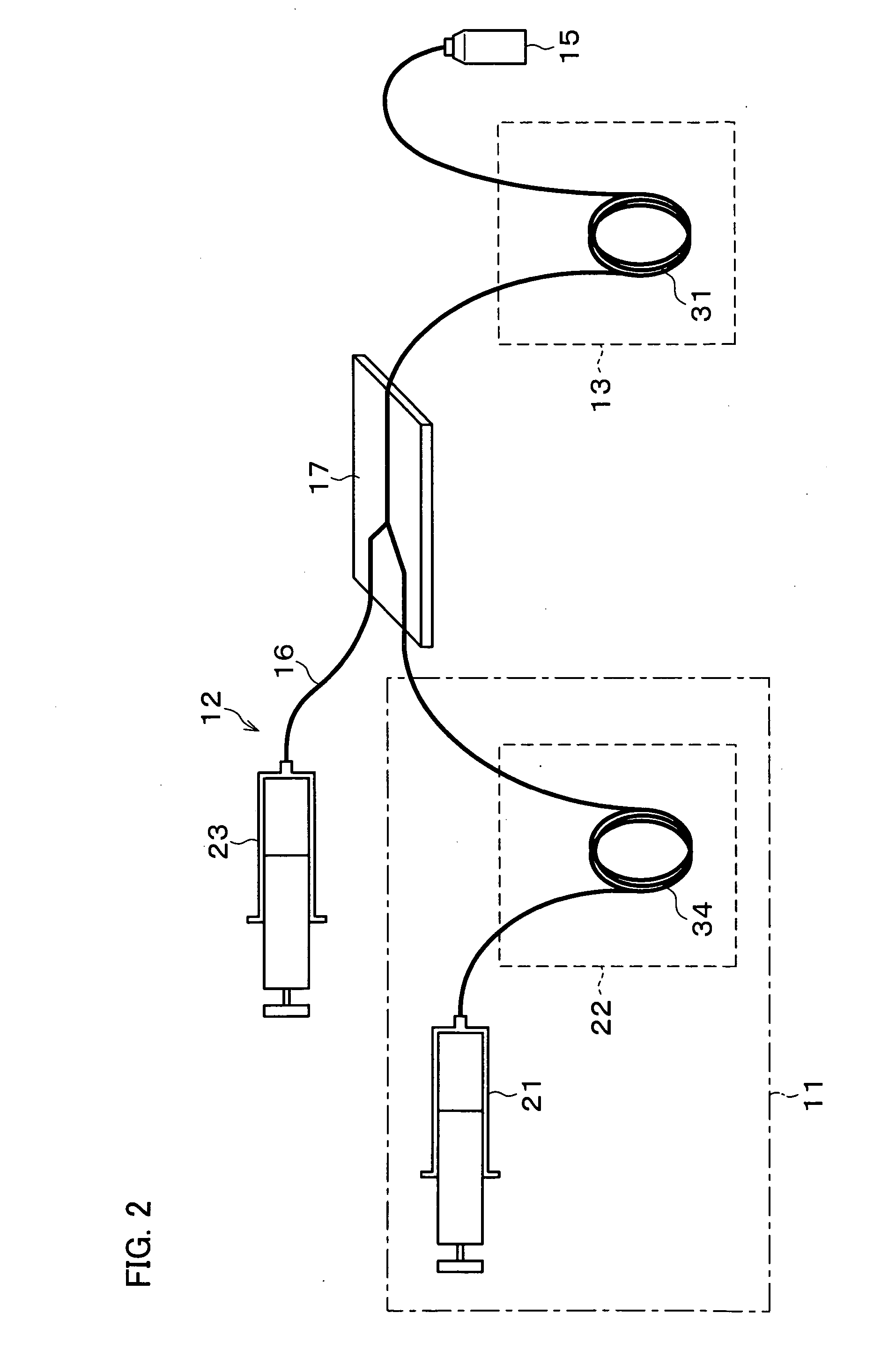
[0149] ZnS coated CdSe fine particles were manufactured by a fine composite particle manufacturing apparatus having the structure shown in FIG. 2.

[0150] A CdSe fine particle base solution (a solution containing a particle-forming precursor) in which 20 g of stearic acid, trioctyl phosphine oxide and trioctyl. phosphine; 266 mg of cadmium acetate, and 494 mg of serene are dissolved was prepared, and the solution was supplied to a syringe pump 21 shown in FIG. 2 until it filled up the pump. Meanwhile, a ZnS coating base solution (composite base solution, or the second phase base material solution) was prepared by mixing 0.4 mmol of dimethyl cadmium and 0.51 mmol of bistrimethylsilyl sulfide with 3 g of TOP, and this solution was supplied to a syringe pump 23 until it filled up the pump.

[0151] The CdSe fine particle base solution was pumped into a capillary (micro flow path 34 of a material-synthesizing reactor 22)...

example 3

Third Example of ZnS Coated CdSe Fine Particle Synthesizing Process

[0153] First, ZnS coated CdSe fine particles were produced by heating a base solution and then immediately subjecting it to mixing by a micro mixer.

[0154] In the same manner as that of Example 2, a CdSe fine particle solution was prepared, and 0.4 mmol of dimethyl cadmium was dissolved therein. The resulting solution was supplied into a syringe pump until it filled up the pump. Meanwhile, a coating base solution (composite base solution, or the second phase base material solution) was prepared by mixing 0.51 mmol of bistrimethylsilylsulfide with 3 g of TOP, and this solution was supplied to a syringe pump 23 until it filled up the pump. Then, the two kinds of solutions were supplied into a micro flow path to run through it so that they were heated to 240° C., and were mixed together by a micro mixer (the mixing is completed in 0.05 seconds). After that, the solutions were supplied into a micro flow path again to r...


PUM

PropertyMeasurementUnit
Fractionaaaaaaaaaa
Timeaaaaaaaaaa
Timeaaaaaaaaaa

Abstract

In the present invention, the fine particle composite process is carried out with the step of reacting fine core particles and a raw material for coating layer by mixing them and continuously supplying a resulting mixture into a micro flow path. The micro flow path is specified to 1-4000 in Reynolds number. With this arrangement, the present invention ensures, in a technology using a reactor having a micro flow path, accurate control of reaction condition, uniformity of coating amount distribution, easy layer formation, and successive production of fine composite particles.

Description

TECHNICAL FIELD [0001] The present invention relates to a method for manufacturing fine composite particle, manufacturing apparatus for fine composite particle, and fine composite particle, particularly to a manufacturing method using a micro flow path, and new fine composite particles effectively manufactured through this manufacturing method. BACKGROUND ART [0002] Nanometer fine particles (nano particles) have come to the front recently as a material for producing stable monotone fluorescent particles, a material of magnetic particles, or as a componential member of tunable light emitting diode, a single-particle transistor, a building block for superdense magnetic storage medium etc. [0003] The demand of the nano particles is particularly increasing recently because of the enlargement of its usage along with the advance in technology. The typical materials of the nano particles are some metals such as gold, platinum, or nickel; some compounds, such as platinum iron, titanium oxid...

Claims


Application Information

Patent Timeline
IPC IPC(8): D06L3/12B05B5/00B82B1/00B82B3/00C01B19/00C01B19/04C01G9/08C09C1/00C09C1/10C23C18/08C23C18/12
CPCB82Y30/00C01B19/007C01P2004/62C01P2004/64C01P2004/84Y10T428/2993C09C1/10C09K11/565C09K11/883Y10T428/2991C09C1/00
Inventor NAKAMURA, HIROYUKIUEHARA, MASATOWANG, HONGZHIMAEDA, HIDEAKIMIYAZAKI, MASAYAYAMAGUCHI, YOSHIKOYAMASHITA, KENICHISHIMIZU, HAZIMELI, XYANYING
Owner NAT INST OF ADVANCED IND SCI & TECH
Learn More