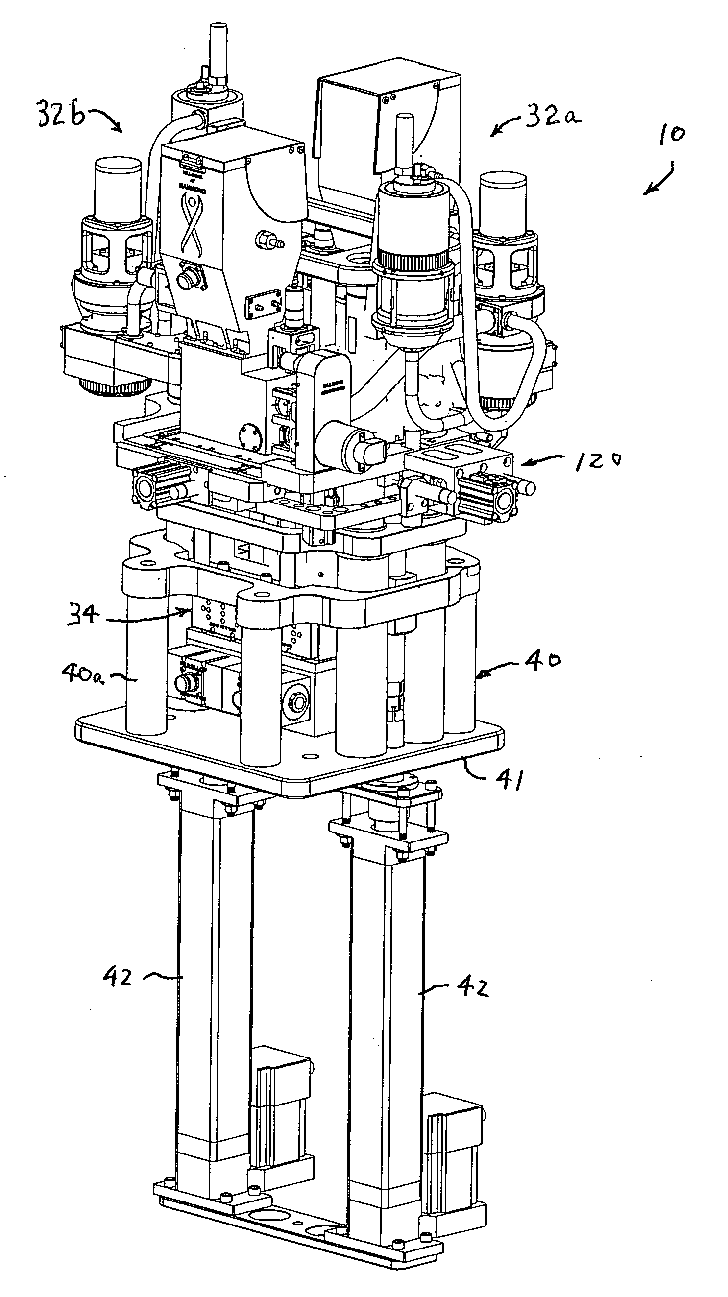
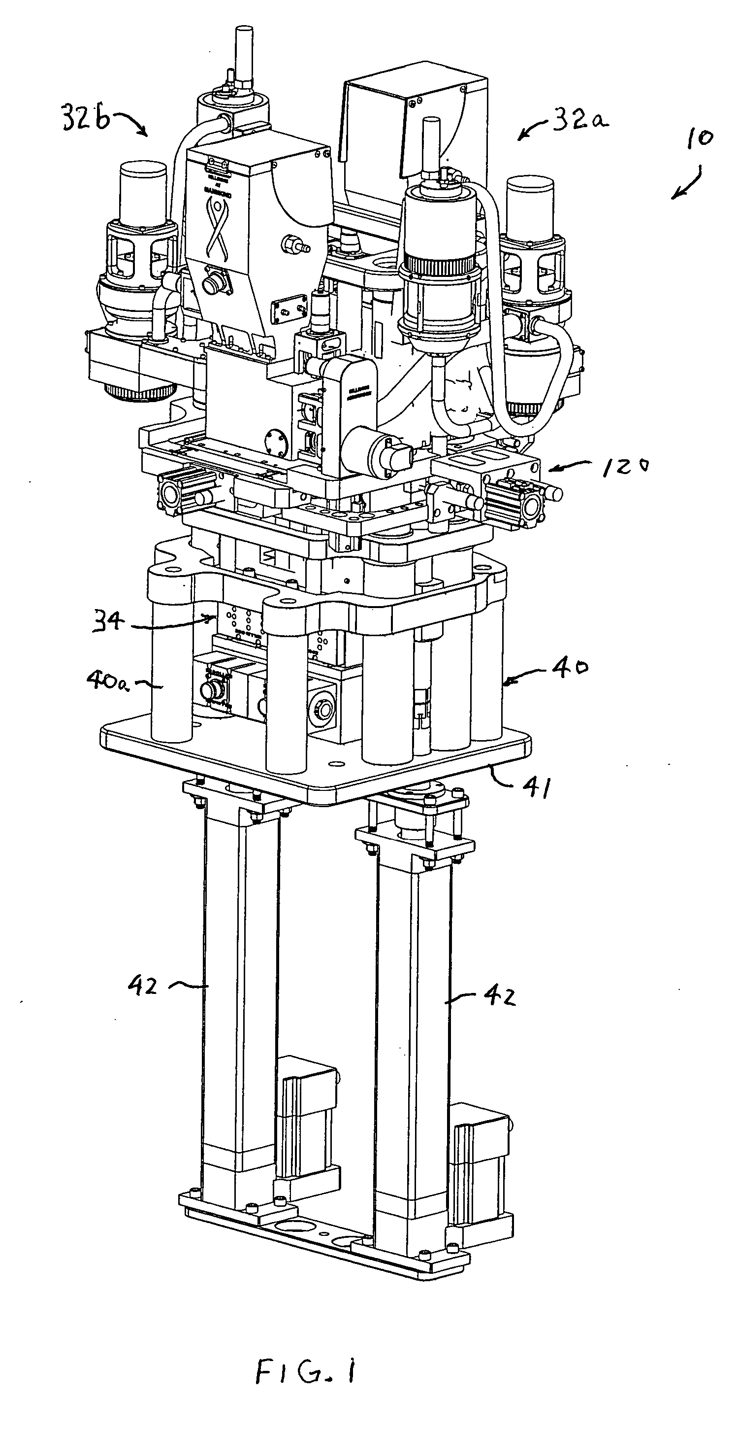
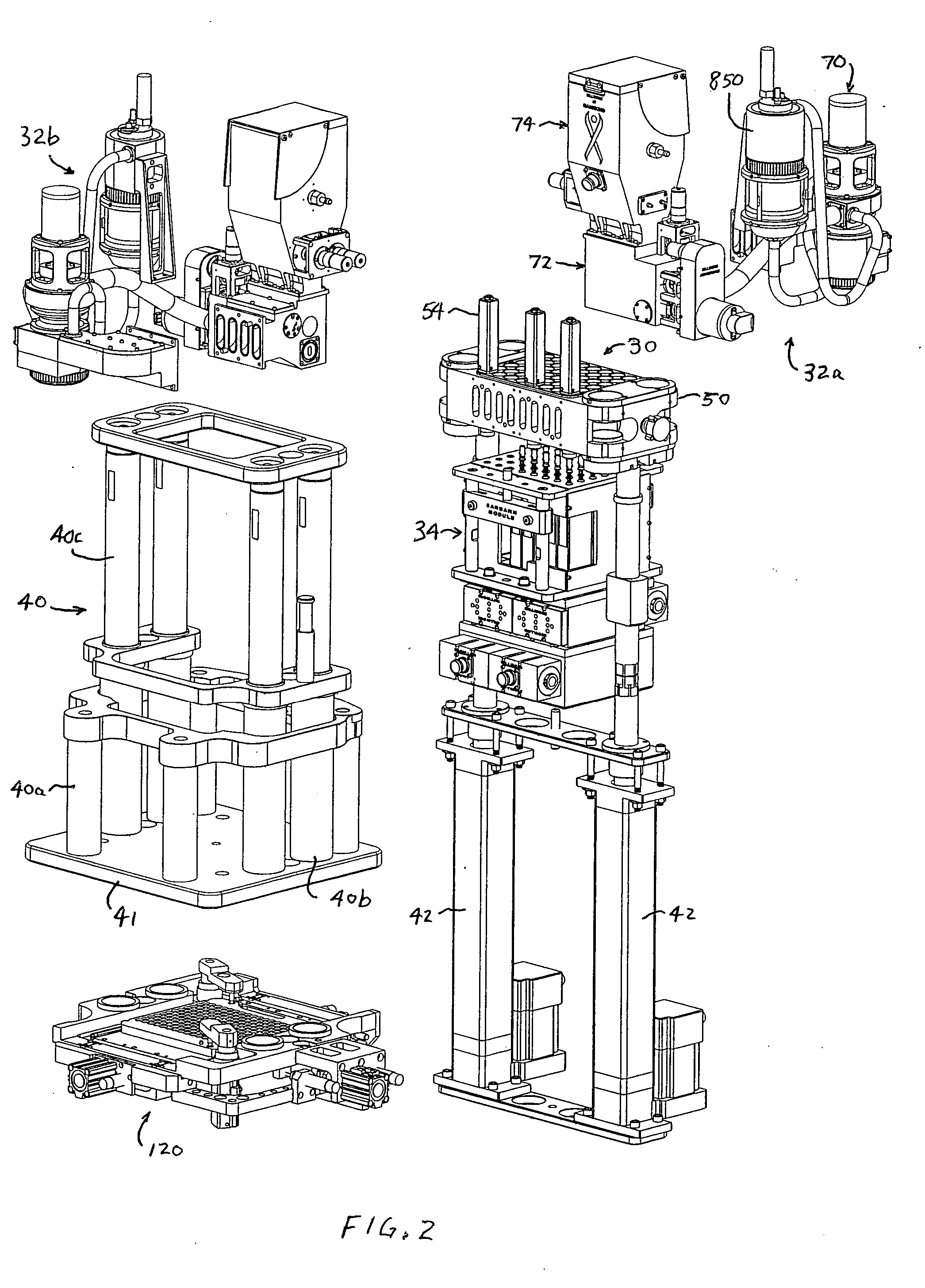
Powder dispenser modules and powder dispensing methods

a technology of powder dispenser modules and powder dispensers, which is applied in the direction of liquid handling, instruments, packaged goods, etc., can solve the problems of not having the desired therapeutic effect, affecting the patient's treatment, and the powder is not cohesive, so as to facilitate regulatory approval, facilitate the effect of cost reduction and compactness

Inactive Publication Date: 2007-06-14
MANNKIND CORP
View PDF61 Cites 48 Cited by
  • Summary
  • Abstract
  • Description
  • Claims
  • Application Information

AI Technical Summary

Benefits of technology

[0028] According to a tenth aspect of the invention, the powder dispensing and sensing apparatus is a highly compact, modular system which is operable both in a research laboratory and in a production plant. This feature facilitates regulatory approval for a common machine and results in cost reduction due to common technical support and training and reduced parts inve

Problems solved by technology

A dose lower than specified may not have the desired therapeutic effect, while a larger than specified dose can have an adverse effect on the patient.
Furthermore, while Technosphere microparticles are highly effective for drug

Method used


Image

  • Powder dispenser modules and powder dispensing methods
  • Powder dispenser modules and powder dispensing methods
  • Powder dispenser modules and powder dispensing methods

Examples


first embodiment

[0182] the weight sensor probe which provides an interface between the weight sensor cell and cartridge 20 is shown in FIG. 22. Probe 112 includes a main body 360 including a post 362 that engages the sensor cell, a head 364 and a cup 366 that accumulates dust and stray powder particles. Probe 112 further includes a dust skirt 370 that deflects dust and powder particles away from the sensor cell and pins 372 for engaging and supporting cartridge 20. The three pins 372 are equally spaced at 120 degree intervals and are designed to elastically flex and then return to their original positions. In addition, the pins are designed to buckle in an overload condition to protect the sensor cell. In the embodiment of FIG. 22, pins 72 are removable for pin height changes for different cartridge tray designs. The small cross-sectional area of the pins reduces the aerodynamic effects of thermal currents which can add bias load forces to precise microgram weight measurements.

second embodiment

[0183] the weight sensor probe which provides an interface between the weight sensor cell and cartridge 20 is shown in FIG. 23. A probe 112a includes a main body 380, including a post 382, a head 384 and a cup 386. Cup 386 accumulates dust and stray powder particles. A dust skirt 390 deflects dust and powder particles away from the sensor cell. In the embodiment of FIG. 23, probe 112a includes pins 392 that are formed integrally with head 384. Each of pins 392 is reinforced with a radial gusset. This configuration adds structural rigidity to the vertically cantilevered lift pins. This configuration also reduces vibration and displacement at the tips of the pins, thus damping the tuning fork effect.

[0184] A first embodiment of powder aerator 72 is shown in FIGS. 24-27 and 28A-28C. A second embodiment of powder aerator 72 is shown in FIGS. 29-32. Powder aerator 72 includes a manifold block 500 which defines gas inlet 78, powder inlet 80 and powder output ports 82. As described above, ...


PUM

PropertyMeasurementUnit
Weightaaaaaaaaaa
Speedaaaaaaaaaa
Proximity effectaaaaaaaaaa

Abstract

Powder dispensing and sensing apparatus and methods are provided. The powder dispensing and sensing apparatus includes a tray support structure to receive a cartridge tray holding cartridges, a powder dispenser assembly including powder dispenser modules to dispense powder into respective cartridges of a batch of cartridges in the cartridge tray, a powder transport system to deliver powder to the powder dispenser modules, a sensor module including sensor cells to sense respective fill states, such as the weights, of each of the cartridges in the batch of cartridges, and a control system to control the powder dispenser modules in response to the respective sensed fill states of each of the cartridges of the batch of cartridges.

Description

CROSS REFERENCE TO RELATED APPLICATION [0001] This application claims priority based on Provisional Application Ser. No. 60 / 738,474, filed Nov. 21, 2005, which is hereby incorporated by reference in its entirety.FIELD OF THE INVENTION [0002] This invention relates to methods and apparatus for dispensing and sensing powder and, more particularly, to methods and apparatus for dispensing precisely-controlled quantities of powder into multiple cartridges and for individually sensing the fill state of each of the cartridges. The powder can contain a drug, and the cartridges can be used in an inhaler. However, the invention is not limited to this application. BACKGROUND OF THE INVENTION [0003] It has been proposed to deliver certain types of drugs to patients by inhalation of a powder as a delivery mechanism. One particular example uses diketopiperazine microparticles known as Technosphere® microparticles. The Technosphere microparticles have a platelet surface structure and can be loaded...

Claims


Application Information

Patent Timeline
IPC IPC(8): B67D5/30A61M11/00B67D7/30
CPCB65B1/12B65B1/30G01G13/24B65B57/145B65B1/32A61M15/00A61J3/02G01G17/00G01G21/23
Inventor POOLE, TRENT A.BONNEAU, DAVID F.FOG, PER B.
Owner MANNKIND CORP
Why Eureka
Try Eureka