Micropattern retardation element

Inactive Publication Date: 2007-06-14
NAT INST OF ADVANCED IND SCI & TECH +1
View PDF26 Cites 14 Cited by
  • Summary
  • Abstract
  • Description
  • Claims
  • Application Information

AI Technical Summary

Benefits of technology

[0032] According to the present invention, a micropattern retardation element can be obtained only by forming a birefringence layer containing birefringence molecules on a liquid crystalline or non liquid crystalline polymer thin film layer having photoactive groups, irradiated by linear polarized light, and by orienting the molecules in a micropattern form. Direct completion of a retardation element became possible also on an unstretchable substrate such as a glass substrate, because of no requirement of stretching operation. In addition, it became possible to arbitrarily alter molecular orientation of a birefringence layer only by changing a polarizing axis of linear polarized light to be irradiated on a polymer thin film, and therefore made it possible to produce a micropattern retardation element with a different polarizing axis, on a substrate. By using a l

Problems solved by technology

This system had a problem that a display is costly and not suitably used in showing three-dimensional view for domestic a

Method used


Image

  • Micropattern retardation element
  • Micropattern retardation element
  • Micropattern retardation element

Examples


example 2

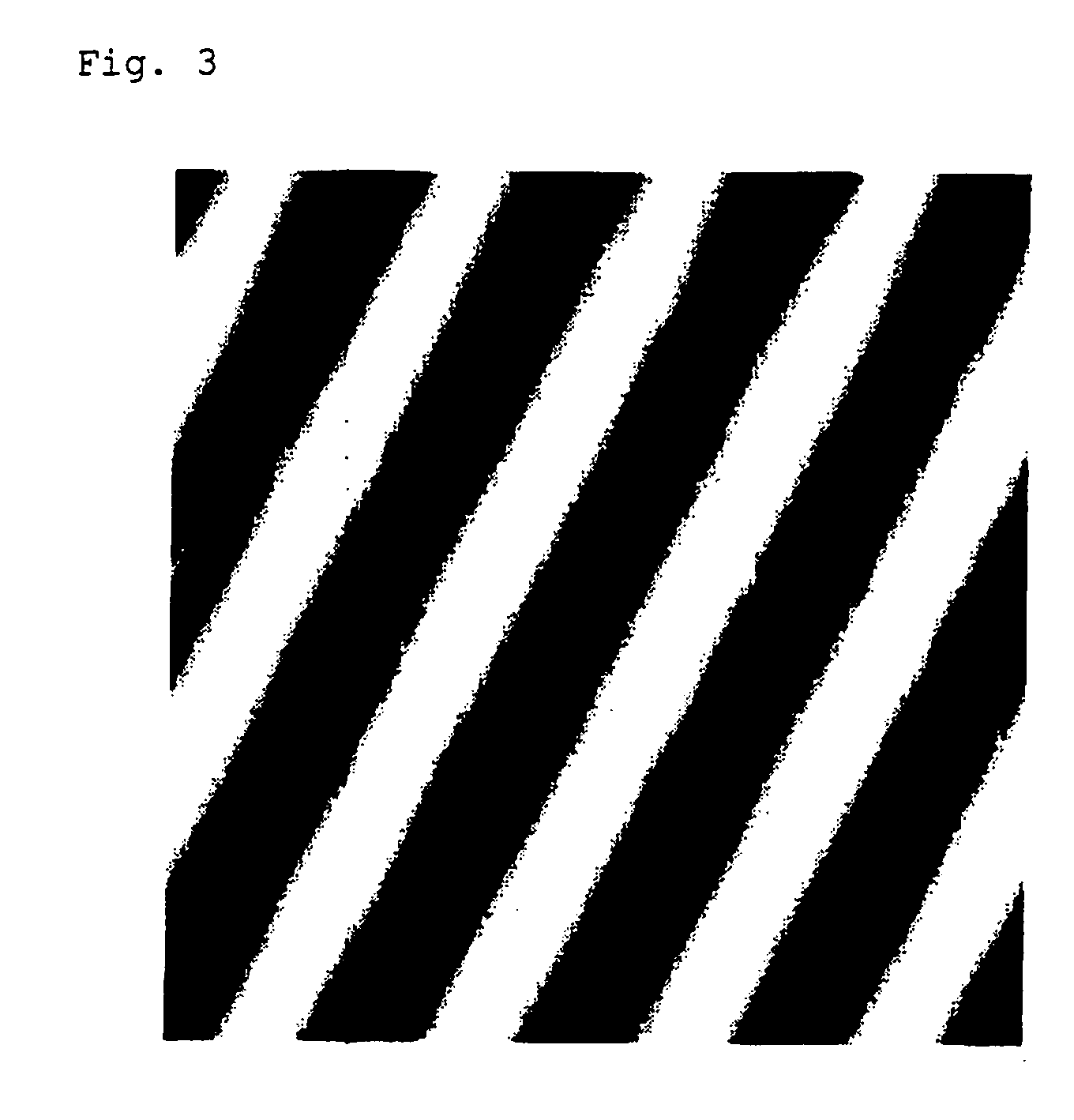
[0092] Similarly as in Example 1, except that direction of a photo mask having stripes was changed, a light irradiated vacant liquid crystal cell was prepared, and into the space of said liquid crystal cell, an about 32% aqueous solution of lithium 4-trans-pentyl cyclohexanoate was charged at about 45° C., and the peripheral of the liquid crystal cell was completely sealed with an epoxy resin. Temperature of the liquid crystal cell was lowered to room temperature (25° C.) and the cell was observed with the polarized light microscope to confirm orientation controlled state. FIG. 3 shows a photo image with the polarized light microscope.

[0093] Lithium 4-trans-pentyl cyclohexanoate, showing lyotropic liquid crystalline property, was synthesized from 4-trans-pentyl cyclohexanoic acid and lithium hydroxide as follows:

[0094] 4-trans-pentyl cyclohexanoate and 19.8 g of 4-trans-pentyl cyclohexanoic acid were dissolved into 100 mL of a 5% aqueous solution of lithium hydroxide by heating un...

example 3

[0096] A light orientation film was produced using poly(1-(2-methacryloyloxymethoxy)-4′-carbonyloxyethylazobenzene), and a liquid crystal cell was produced similarly as in Example 1, and into the space of 2 glass substrates of the light irradiated liquid crystal cell, an about 32% aqueous solution of lithium 4-trans-pentyl cyclohexanoate was charged, and by light orientation of a lyotropic liquid crystalline phase of lithium 4-trans-pentyl cyclohexanoate, good orientation state was obtained.

example 4

[0097] According to Example 1, a glass substrate having a polyamide thin film containing photoactive groups was formed, and said glass substrate was irradiated by linear polarized light, obtained by passing visible light produced by using a cut-off filter at 400 nm, through a polarizing plate, using a high pressure mercury lamp for 1 minute from a distance of 50 cm from said substrate, to unidirectionally orient a molecular axis of photoactive groups. Then, the whole surface of the glass substrate was covered with a photo mask having stripes in about 70 μm interval, so that the stripe direction is in parallel to electric vector of linear polarized light used in the first irradiation, and over which linear polarized light rotated by 45 degree from the first linear polarized light was irradiated to prepare an exposed substrate.

[0098] Then, a solution dissolved with 5 parts of sodium cromoglycate (produced from Shiono Chemical Co., Ltd.), 0.2 parts of Emal 20 C (product name: produced...


PUM

PropertyMeasurementUnit
Polarized lightaaaaaaaaaa
Thermotropismaaaaaaaaaa
Birefringenceaaaaaaaaaa

Abstract

The present invention relates to a micropattern retardation element requiring no stretch processing and no extremely high positioning accuracy in cutting films, and the like, and having the retardation region controlled in width of a micron unit, and a producing method therefore. Said micropattern retardation element can be obtained by forming a liquid crystalline or non liquid crystalline polymer thin film layer having photoactive groups, on a substrate, and then, after orientation treatment in a micropattern form, forming a birefringence layer so as to contact with said polymer thin film layer, so that birefringence molecules of said birefringence layer are oriented according to orientation of photoactive groups in said thin film. Said retardation element is used in a three-dimensional display, and the like.

Description

TECHNICAL FIELD [0001] The present invention relates to a novel micropattern retardation element and a method for producing the same, and further a liquid crystal display element enabling three-dimensional view by using the micropattern retardation element. BACKGROUND ART [0002] Various methods have been proposed in relation to technology of three-dimensionally view image (three-dimensional view). One of such technology, two-lens type three-dimensional view using polarized light, is one also called as a polarized light glasses system. This is an observation system, wherein image obtained from a right eye and a left eye in wearing state of glasses each using a polarizing plate having an orthogonal polarizing axis on each eye, is one having binocular parallax, and image information at right and left sides is each assigned to right and left eyes by a polarizing plate of observer's glasses, by means of orthogonalizing each polarized light plane of light. To view image with different pol...

Claims


Application Information

Patent Timeline
IPC IPC(8): C09K19/00B05D1/32C08F2/46G02B5/30G02B27/00G02B30/25G03B35/26
CPCG02B5/3083G02B27/0087Y10T428/1005G03B35/26Y10T428/1036G02B27/26C09K2323/02C09K2323/03G02B30/25
Inventor MATSUNAGA, DAISAKUHASHIMOTO, MASANORIRUSLIM, CHRISTIANTAMAKI, TAKASHIICHIMURA, KUNHIRO
Owner NAT INST OF ADVANCED IND SCI & TECH
Why Eureka
Try Eureka