Hydrophobic catalyst layer for polymer electrolyte fuel cell and method of producing the same, and polymer electrolyte fuel cell and method of producing the same

a technology of electrolyte fuel cell and hydrophobic catalyst, which is applied in the manufacture of cell components, final product manufacturing, electrochemical generators, etc., can solve the problems of reduced utilization factor, reduced effective surface area, and reduced so as to increase the utilization factor of catalyst, the effect of low cost and additional stability

Inactive Publication Date: 2007-06-14
CANON KK
View PDF6 Cites 19 Cited by
  • Summary
  • Abstract
  • Description
  • Claims
  • Application Information

AI Technical Summary

Benefits of technology

[0036] Further, the present invention can provide a polymer electrolyte fuel cell having additionally stable characteristics at a low cost.
[0037] Furthermore, according to the present invention, a contact area between a catalyst and an electrolyte, that is, an effective surface area that can contribute to a catalytic reaction can be increased, whereby the utilization factor of the catalyst can be increased.
[0038] As a result, the simultaneous achievement of the impartment of hydrophobicity and an increase in utilization factor of a catalyst which has been conventionally difficult is enabled. In addition, the increase in utilization factor of the catalyst can reduce a catalyst carrying amount, so that a production cost can be reduced.
[0039] In addition, the present invention can provide, at a low cost, a polymer electrolyte fuel cell having stable electricity generation property by using the above cata

Problems solved by technology

Accordingly, when conventional hydrophobic fine particles are used, the hydrophobicity of a catalyst layer improves, but there arises a problem in that part of the hydrophobic fine particles enter a gap between adjacent catalyst particles or between a catalyst and the electrolyte, so that

Method used


Image

  • Hydrophobic catalyst layer for polymer electrolyte fuel cell and method of producing the same, and polymer electrolyte fuel cell and method of producing the same
  • Hydrophobic catalyst layer for polymer electrolyte fuel cell and method of producing the same, and polymer electrolyte fuel cell and method of producing the same
  • Hydrophobic catalyst layer for polymer electrolyte fuel cell and method of producing the same, and polymer electrolyte fuel cell and method of producing the same

Examples


example 1

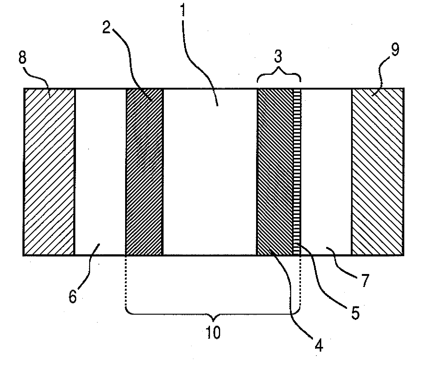
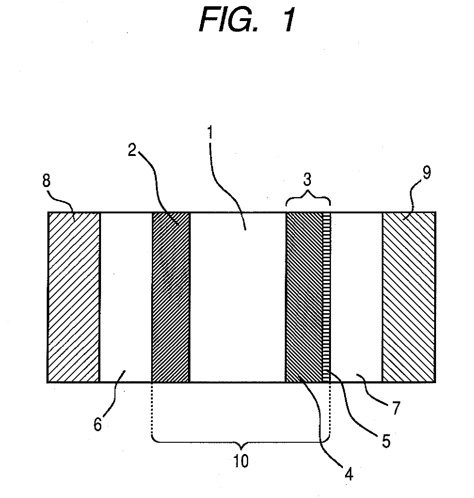
[0106] In this example, a polymer electrolyte fuel cell having the constitution shown in FIG. 1 as the embodiment of the present invention was produced.

[0107] Hereinafter, the production steps of the polymer electrolyte fuel cell according to this example will be described in detail.

[0108] (Step 1)

[0109] A gold thin film having a thickness of 50 nm was formed by means of an electron beam vacuum evaporation method on a PTFE sheet (NITFLON manufactured by NITTO DENKO CORPORATION) as a layer to be transferred onto a polymeric electrolyte membrane. A porous platinum oxide layer having a thickness of 2 μm was formed thereon by means of a reactive sputtering method. The reactive sputtering was performed under the conditions of: a total pressure of 5 Pa; an oxygen flow rate ratio (QO2 / (QAr+QO2) ) of 70%; a substrate temperature of 25° C.; and an RF input power of 5.4 W / cm2.

[0110] (Step 2)

[0111] Subsequently, the porous platinum oxide layer was brought into contact with the steam of 2,...

example 3

[0152] (Step 1)

[0153] A porous platinum oxide layer having a thickness of 2 μm was formed by means of a reactive sputtering method on a surface composed of carbon fine particles of carbon cloth (LT-1400W manufactured by E-TEK) as a substrate for a catalyst layer serving also as a gas-diffusion layer. The reactive sputtering was performed under the conditions of: a total pressure of 5 Pa; an oxygen flow rate ratio (QO2 / (QAr+QO2)) of 70%; a substrate temperature of 25° C.; and an RF input power of 5.4 W / cm2.

[0154] (Step 2)

[0155] Subsequently, the composite of the porous platinum oxide layer and the gas-diffusion layer was brought into contact with the steam of TMCTS (having a partial pressure of 0.05 Pa) at 25° C. for 5 minutes, whereby a methylsiloxane polymer was formed on the surface of a platinum oxide. In Example 3, a heat treatment like Example 1 was not performed as a subsequent step.

[0156] (Step 3)

[0157] Subsequently, the obtained catalyst layer was subjected to a reducti...


PUM


Abstract

Provided is a hydrophobic catalyst layer for a polymer electrolyte fuel cell to which hydrophobicity is imparted so that the dissipation property of produced water is improved and which simultaneously has an increased effective surface area and an increased utilization ratio of a catalyst, and a method of producing the same. The catalyst layer for a polymer electrolyte fuel cell includes a catalyst obtained by reducing a platinum oxide, a hydrophobic agent, and a proton conductive electrolyte, wherein the hydrophobic agent is mainly composed of alkylsiloxane. An Si compound containing a hydrophobic substituent is brought into contact with a platinum oxide to subject the Si compound to hydrolysis and a polymerization reaction by the catalytic action of the platinum oxide, and then it is reduced, thereby obtaining a hydrophobic catalyst layer carrying an alkylsiloxane polymer.

Description

[0001] This application is a continuation of International Application No. PCT / JP2006 / 309356, filed Apr. 28, 2006, which claims the benefit of Japanese Patent Application No. 2005-132957, filed Apr. 28, 2005. BACKGROUND OF THE INVENTION [0002] 1. Field of the Invention [0003] The present invention relates to a hydrophobic catalyst layer for a polymer electrolyte fuel cell and a method of producing the same, and a polymer electrolyte fuel cell and a method of producing the same. [0004] 2. Description of the Related Art [0005] A polymer electrolyte fuel cell is expected to be an energy generating apparatus in the future because the cell has high energy conversion efficiency, and is clean and quiet. Investigation has been recently conducted into the application of the polymer electrolyte fuel cell to not only a power source for an automobile, a domestic generator, or the like but also a power source for, for example, a small-size electrical apparatus such as a portable phone, a noteboo...

Claims


Application Information

Patent Timeline
IPC IPC(8): H01M4/92H01M4/88
CPCH01M4/8657H01M4/8663H01M4/8871H01M4/8892H01M4/92H01M4/926H01M8/04291H01M2008/1095Y02E60/50H01M4/0402H01M4/366Y02E60/10Y02P70/50H01M4/86H01M4/88H01M8/10
Inventor YAMADA, KAZUHIROMIYAZAKI, KAZUYA
Owner CANON KK
Why Eureka
Try Eureka