

Technique for stress redistribution
a stress redistribution and stress technology, applied in the field of minimizing weld joint variability and reducing stresses, can solve the problems of high material and cask temperature, expansion and distortion of the cask portion, and unknown thermal expansion and distortion of the cask, so as to minimize or eliminate the residual stress in the joint
- Summary
- Abstract
- Description
- Claims
- Application Information
AI Technical Summary
Benefits of technology
Problems solved by technology
Method used
Image


Examples
Embodiment Construction
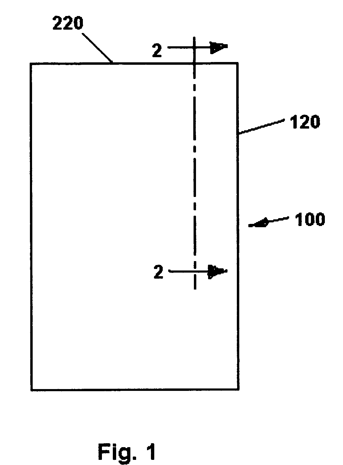
[0029]FIG. 1 is an outline drawing representing a cylindrical nuclear waste cask 100. In FIG. 1, the cask 100 comprises a cylindrical outer corrosion barrier 120 and a flat closure 220.
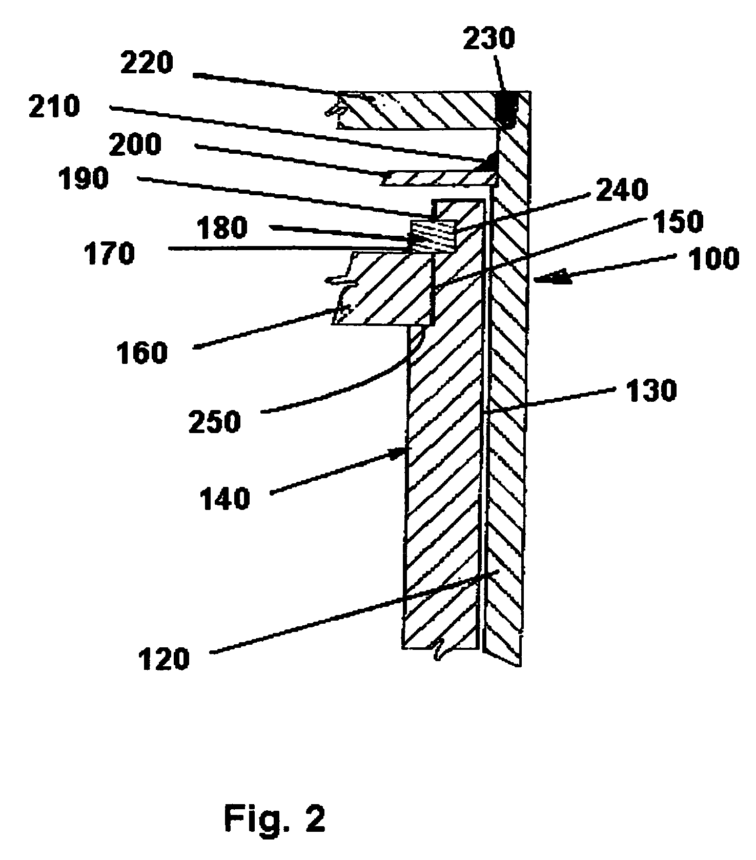
[0030]FIG. 2 is a partial sectional view through a wall of the cask 100 taken along the section line 2-2 in FIG. 1. Referring to FIG. 2, the cask 100 comprises the outer corrosion barrier 120, an inner vessel 140 separated from the corrosion barrier 120 by space 130. The inner vessel 140 has a first radial shoulder 250, a radial face 240, axially extending surface 150, and an inwardly facing C-shaped groove 240. The principles of this invention are applicable to any weldable materials. However, the United States Department of Energy requirements for the design and construction certain nuclear waste cask call for a Nickel alloy outer corrosion barrier made from Alloy 22 (60% nickel, 22% chromium, 13% molybdenum, and 3% tungsten) and an inner vessel made from stainless steel (316NG) with additional lim...
PUM
| Property | Measurement | Unit |
|---|---|---|
| Temperature | aaaaa | aaaaa |
| Residual stress | aaaaa | aaaaa |
Abstract
Description
Claims
Application Information