
Toner, developer, and image forming apparatus

a technology of image forming apparatus and developer, which is applied in the direction of instruments, developers, optics, etc., can solve the problems of complex fixing system, increased manufacturing and operation costs, and increased fixation device size, and achieves thermostable preservability, good combination of low temperature fixability and hot offset resistan

Active Publication Date: 2007-06-21
RICOH KK
View PDF1 Cites 54 Cited by
  • Summary
  • Abstract
  • Description
  • Claims
  • Application Information

AI Technical Summary

Benefits of technology

[0034] Accordingly, an object of the present invention is to provide a toner having a good combination of low temperature fixability, hot offset resistance, and thermostable preservability.
[0035] Another object of the present invention is to provide a developer which does not cause carrier adherence.
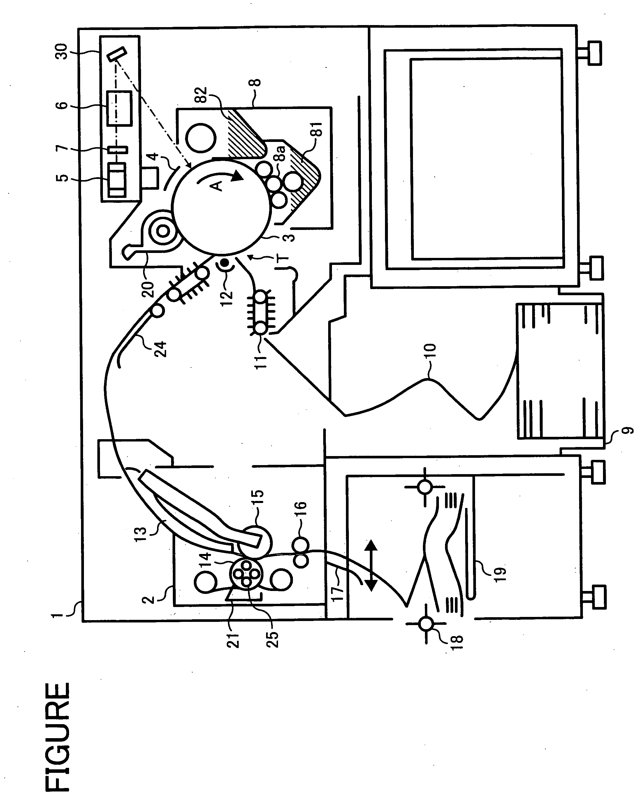
[0036] Another object of the present invention is to provide a high-speed image forming apparatus which can produce high quality images for a long period of time.

Problems solved by technology

However, the contact heat fixing methods tend to cause an offset problem in that part of a fused toner image is adhered and transferred to the surface of the heat roller, and then part of the toner image is retransferred to the following sheet of a transfer material.
However, in the latter case, since a fixing device needs a fixing oil applying system, the fixing device upsizes and the fixing system becomes complicated.
As a result, manufacturing costs and operation costs increase, and various troubles are likely to be caused.
However, in this case, a toner cannot be sufficiently melted, i.e., the toner cannot be sufficiently fixed.
In addition, as the glass transition temperature of the resin having lower softening point increases, the thermostable preservability of the toner improves, but the toner cannot have a good combination of low temperature fixability and hot offset resistance even if the amount of the resin having lower softening point is increased.
Moreover, since the difference between the softening point of the resin having lower softening point and the minimum fixing temperature at which the toner can be fixed is too large, the toner cannot be sharply melted at such a low fixing temperature.
However, chargeability of such a toner is changed due to existence of the particulate inorganic material.
In addition, since elastic modulus of the toner is also changed due to existence of the particulate inorganic material, the shapes of the toner particles vary, and therefore a problem such that each of the toner particles has different fixing property is caused.
As a result, a problem such that the carrier adheres to a non-image portion of the latent image formed on the latent image bearing member tends to be caused.
When the carrier adherence occurs, the quality of the produced image deteriorates.
For example, when carrier particles adhered to an image bearing member are transferred and fixed onto a transfer material (such as a paper), an image having noise is produced.
The carrier particles adhered on the image bearing member cause a problem such that abnormal images such as white spots are produced.
Another problem is also caused such that the carrier particles adhered on the image bearing member damage image forming members arranged around the image bearing member.
However, it is still difficult to completely prevent carrier adherence even in such an image forming method.
There is a problem such that a part of a toner on the developer bearing member cannot move to an image bearing member because the developing bearing member has too strong a magnetic force.
As a result, fogging is observed on the resultant images.
In addition, manufacturing cost of the apparatus increases because of loading magnetic poles therein.

Method used


Image

  • Toner, developer, and image forming apparatus
  • Toner, developer, and image forming apparatus

Examples


example 1

[0247] The following components are mixed using a HENSCHEL MIXER.

Amorphous polyester (A1)55 partsAmorphous polyester (D1)20 partsCrystalline polyester (C1)25 partsCarbon black10 parts(MOGUL L from Cabot Corporation)Charge controlling agent 2 parts(BONTRON N-04 from Orient ChemicalIndustries, Ltd.)Carnauba wax 3 parts(CARNAUBA WAX C1 from S. Kato & Co.,melting point of 84 °C.)Fatty acid amide 5 parts(KAOWAX EB-FF from Kao Corporation,melting point of from141.5 to 146.5 °C.)

[0248] The mixture is melt-kneaded using a double-axis extruder under the following conditions. [0249] Rotation speed: 200 rpm [0250] Heating temperature: 100° C. [0251] Feeding speed: 15 kg / h

[0252] The kneaded mixture is rolled (i.e., extended by application of pressure) by a roller, and then subjected to cooling. Next, the mixture is subjected to coarse pulverization and fine pulverization using a TURBO-MILL, followed by classification. Thus, mother toner particles having a volume average particle diameter of ...

example 2

[0254] The procedure for preparation of the toner (1) is repeated except the carnauba wax is replaced with a polyethylene wax (LEL800 from Sanyo Chemical Industries, Ltd., melting point of 133° C.). Thus, a toner (2) is prepared.

example 3

[0255] The procedure for preparation of the toner (1) is repeated except “3 parts of the carnauba wax” is replaced with “2 parts of the carnauba wax and 2 parts of the polyethylene wax”. Thus, a toner (3) is prepared.


PUM

PropertyMeasurementUnit
Temperatureaaaaaaaaaa

Abstract

A toner is provided including a binder resin; a release agent; a colorant; and a fatty acid amide compound, wherein the binder resin includes: an amorphous polyester (A) having a softening point of from 70 to 140° C.; an amorphous polyester (B) having a softening point of from 120 to 190° C.; and a crystalline polyester (C), and wherein the following relationship is satisfied: TmC<Tm(Asp), wherein TmC represents a softening point of the crystalline polyester (C) and Tm (Asp) represents a softening point of the fatty acid amide compound; and a developer and an image forming apparatus using the toner.

Description

BACKGROUND OF THE INVENTION [0001] 1. Field of the Invention [0002] The present invention relates to a toner and a developer for use in electrophotography. In addition, the present invention also relates to an image forming apparatus using the toner. [0003] 2. Discussion of the Background [0004] Electrophotography is generally used for image forming apparatuses such as laser printers and dry electrostatic copiers. In electrophotography, an image is formed as follows: [0005] (1) uniformly charging a photoconductive insulating layer (i.e., a charging process); [0006] (2) partially irradiating the photoconductive insulating layer with light to dissipate charges, to form an electrostatic latent image (i.e., an irradiating process); [0007] (3) adhering a toner, which is typically a colored and charged particulate material, to the electrostatic latent image to form a visible image (i.e., a developing process); [0008] (4) transferring the visible image onto a transfer material such as a tr...

Claims


Application Information

Patent Timeline
IPC IPC(8): G03G9/087
CPCG03G9/081G03G9/08755G03G9/08795G03G9/08797G03G9/09733
Inventor UMEHARA, KEN
Owner RICOH KK
Learn More