
Antireflection film, polarizing plate, method for producing them, liquid cryatal display element, liquid crystal display device, and image display device

a technology of antireflection film and polarizing plate, which is applied in the direction of polarising elements, instruments, synthetic resin layered products, etc., can solve the problems of long heating time, difficult to obtain, and low-refractive index materials, so as to reduce weight and cost, the effect of reducing weigh

Active Publication Date: 2007-06-28
FUJIFILM CORP
View PDF37 Cites 190 Cited by
  • Summary
  • Abstract
  • Description
  • Claims
  • Application Information

AI Technical Summary

Benefits of technology

[0021] Accordingly, an object of the invention is to provide an antireflection film that satisfies all the requirements of good antireflection capability, good scratch resistance and good stain resistance and further satisfies high producibility, and is producible in a simplified manner and inexpensively.
[0201] Further, the invention provides a polarizing plate provided with the above-mentioned antireflection film of the invention. In the liquid crystal display device of the invention that is provided with the antireflection film or the polarizing plate has good visibility and has good scratch resistance and stain resistance since the antireflection film is disposed on the outermost surface of the panel thereof.

Problems solved by technology

In fact, however, all these methods are problematic in that the materials are difficult to obtain and are unstable and their films are not strong and are not resistant to staining, and sufficiently satisfactory low-refractive index materials could not as yet obtained.
However, this has significant limitations in that (1) curing the films requires long-time heating and the production load is therefore great, and (2) the films are not resistant to saponification solution (alkali-processing solution), and saponification of the surface of transparent plastic film substrates after the formation of antireflection film thereon could not be carried out.
In addition, the films are not satisfactorily resistant to staining.
However, most of such compounds are often in a trade-off relation, or that is, when one of the requirements is improved, then the other is worsened.
Accordingly, it is difficult to satisfy all the requirements of refractive index reduction and improvement of scratch resistance and stain resistance.
However, the high-refractive index hard-coat layer causes film color mottles since the refractive index difference between the layer and the support is large, and the wavelength dependency of the refractive index of the film greatly increases.
The method may be effective in some degree for the improvement of scratch resistance of the films, but is still unsatisfactory in that films essentially not having high strength and high interfacial adhesiveness could not be improved to have sufficient scratch resistance by the method.
However, this is also problematic in that, when such a thin-film system is cured in an atmosphere in which the oxygen concentration is near to that in air (oxygen concentration: about 20% by volume), the reactive group in the film could not well react owing to curing failure and therefore the scratch resistance of the cured film is not good.
In addition, since the low-refractive index layer in JP-2003-292831 is not processed to be resistant to staining, this is still problematic in that stains such as finger marks or water marks may readily adhere to the films and the stains adhered to them are difficult to wipe away.
These are excellent as a low-refractive index material, but it has been found that, when they are used in a low-refractive index layer of antireflection films, their adhesiveness is poor and they detract from the commercial value of the outermost film of displays, and therefore, their amount to be used must be limited.
However, since this requires a silicone oxide film to be formed in a mode of CVD, its producibility is low when compared with wet-coated films.
However, in the antireflection film, the thickness of the constitutive layers of the multi-layered product is constant in each layer, and therefore, in principle, the antireflection film could not completely attain its function of antireflection in the entire region of visible light.
As a result, this is problematic in that the reflected light exhibits a specific color hue and it detracts from the display quality of devices.

Method used


Image

  • Antireflection film, polarizing plate, method for producing them, liquid cryatal display element, liquid crystal display device, and image display device
  • Antireflection film, polarizing plate, method for producing them, liquid cryatal display element, liquid crystal display device, and image display device
  • Antireflection film, polarizing plate, method for producing them, liquid cryatal display element, liquid crystal display device, and image display device

Examples


first aspect and second embodiment

of the Invention

(High (Middle)-Refractive Index Layer)

[0409] When a high-refractive index layer is in the antireflection film of the invention, then its refractive index is preferably from 1.65 to 2.40, more preferably from 1.70 to 2.20. When a middle-refractive index layer is in the film, then its refractive index is so controlled that it could be between the refractive index of the low-refractive index layer and that of the high-refractive index layer. Preferably, the refractive index of the middle-refractive index layer is from 1.55 to 1.80. Also preferably, the haze of the high-refractive index layer and the middle-refractive index layer is at most 3%.

[0410] For the high-refractive index layer and the middle-refractive index layer in the invention, preferably used is a cured product of a composition that is prepared by dispersing inorganic fine particles having a high refractive index in a monomer, an initiator and an organic substituted silicon compound such as those describ...

third embodiment

of the Invention

[0454] (Light-Scattering Layer) The light-scattering layer is formed for the purpose of imparting a light diffusion property owing to at least any of surface light scattering or internal light scattering, to the film, and for the purpose of imparting thereto a hard coat property of improving the scratch resistance of the film. Accordingly, it is desirable that the light-scattering layer contains a translucent resin for imparting the hard coat property to the film and translucent particles for imparting the light-scattering property thereto, and may optionally contain an inorganic filler which is for making the layer have a high refractive index, for preventing the layer from being shrunk after crosslinking, and for increasing the mechanical strength of the layer.

[0455] For imparting the hard coat property to the film, the thickness of the light-scattering layer is preferably from 1 to 10 μμ, more preferably from 2 to 6 μm. When its thickness falls within the range a...

fourth embodiment

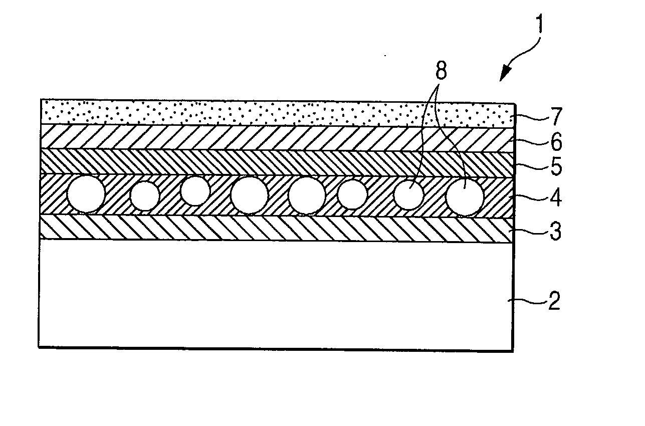
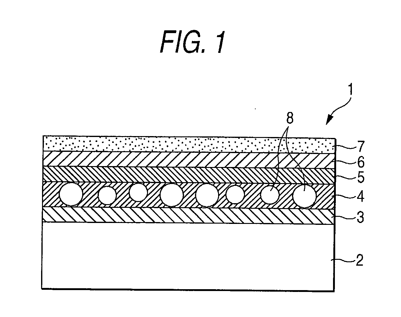
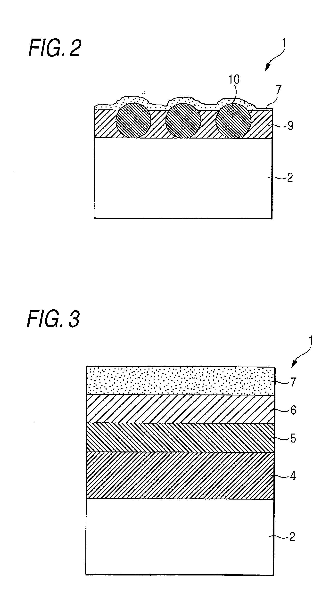
[0537] The antireflective film in the invention comprises the cellulose acylate film support having provided thereon by coating a light-diffusing layer or a high-refractive index layer, and a antireflective layer comprising a low-refractive index layer having a refractive index lower than that of the support.

[0538] Further, it is preferred for the antireflective film in the invention to have an average reflectivity (mirror reflectivity) in wavelengths of from 380 to 680 nm of 3% or less, and a haze value of from 0.1 to 60% (when the antireflective film takes the constitution of a light-diffusing layer and a low-refractive index layer, the haze value is from 10 to 60%, and when the constitution comprises a high-refractive index layer and a low-refractive index layer, from 0.1 to 5%), more preferably the average reflectivity is 2% or less and the haze value is from 0.2 to 55% (in the case of the constitution of a light-diffusing layer and a low-refractive index layer, the haze value ...


PUM

PropertyMeasurementUnit
refractive indexaaaaaaaaaa
surface free energyaaaaaaaaaa
scratch resistanceaaaaaaaaaa

Abstract

To provide an antireflection film which is easily and inexpensively producible and which has an antireflection property, a scratch resistance and a stain resistance in a sufficient level, and a polarizing plate and a liquid crystal display device utilizing the antireflection film of such excellent ability, the antireflection film includs a transparent support and a low-refractive index layer having a lower refractive index than the transparent support, wherein the low-refractive index layer is an outermost layer, and the low-refractive index layer contains a hollow silica particle and a compound that reduces a surface free energy of the outermost layer.

Description

TECHNICAL FIELD [0001] The invention relates to an antireflection film, a polarizing plate comprising the same, and a method for producing them. The invention also relates to a liquid crystal display element and an image display device such as a liquid crystal display device. BACKGROUND ART [0002] In general, an antireflection film is disposed on the outermost surface of image display devices such as cathode-ray tube display devices (CRT), plasma display panels (PDP), electroluminescent display devices (ELD) and liquid crystal display devices (LCD). This is for preventing contrast reduction or image reflection owing to external light reflection on the displays, generally having a function of reflectivity reduction owing to light scattering on surface protrusions or to light interference of multi-layered thin films. [0003] The antireflection film is generally produced by forming, on a transparent support, a film of a low-refractive index layer having a suitable thickness and having a...

Claims


Application Information

Patent Timeline
Patent Type & Authority Applications(United States)
IPC IPC(8): G02B1/10B32B7/02B32B27/18C08F214/28C08F216/12G02B5/30
CPCG02B1/111Y10T428/1045Y10T428/105C09K2323/033C09K2323/035B32B2457/202B32B7/023
Inventor IKEDA, AKIRAMURAMATSU, YUUZOUNAKAMURA, KAZUHIROKATO, EIICHI
Owner FUJIFILM CORP
Learn More