Riding floor polishing machine

Inactive Publication Date: 2007-07-05
CAREX POWER TECH
View PDF45 Cites 23 Cited by
  • Summary
  • Abstract
  • Description
  • Claims
  • Application Information

AI Technical Summary

Benefits of technology

[0018] A riding floor polishing machine with dust and exhaust filtering apparatus is disclosed. The riding floor polishing machine provides a vehicle-driven surface processing apparatus capable of performing a large scale surface polishing operation in an indoor setting with reduced dust accumulation and reduced exhaust emission to the working environment. The riding floor polishing machine includes generally a grinder assembly, an exhaust control device, and a dust collection device, each carried by a vehicle. The vehicle includes a chassis, a combustion engine mounted on the chassis, and an exhaust port for releasing exhaust from the combustion engine. The vehicle provides mobility to the riding floor polishing machine and includes an electric generator to provide power for operating the various functions of the grinder assembly, the exhaust control

Problems solved by technology

A large scale surface polishing operation is often time consuming, labor intensive, and tiresome.
However, use of a conventional combustion engine vehicle results in the emission of exhaust fumes.
When working indoors, this exhaust typically accumulates within the room housing the working surface, often resulting in significantly increased concentrations of toxins immediately surrounding the working surface.
The excessive presence of combustion-engine exhaust leads to an uncomfortable and potentially dangerous work environment for the user of the surface polishing machine.
Therefore, such use of a vehicle in assisting with large scale surface polishing has been previously limited to outdoor operations or other significantly well ventilated environments.
Furthermore, there has been a perenni

Method used


Image

  • Riding floor polishing machine
  • Riding floor polishing machine
  • Riding floor polishing machine

Examples


Embodiment Construction

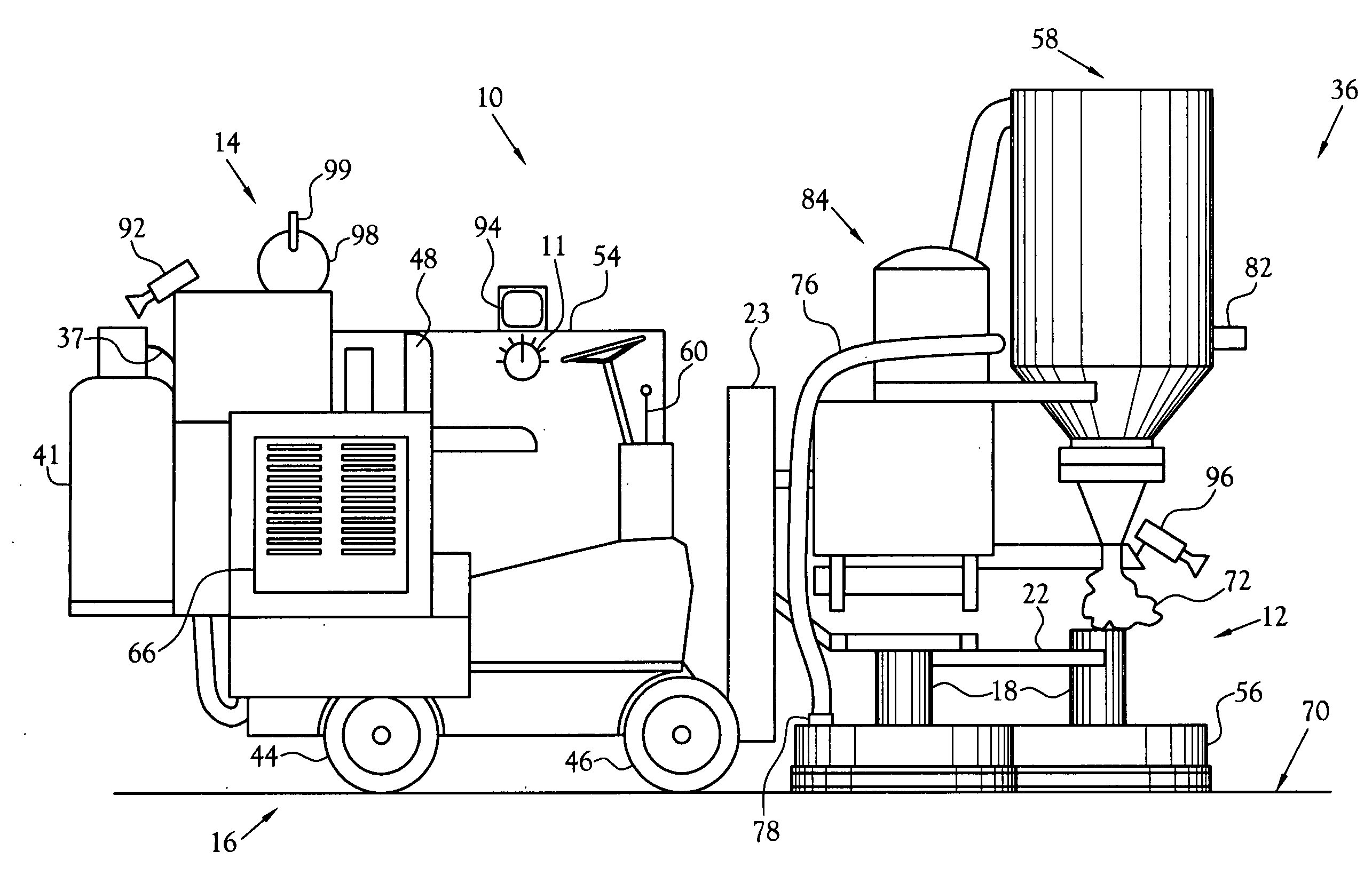
[0029] A riding floor polishing machine with dust and exhaust filtering apparatus is disclosed. The riding floor polishing machine, illustrated at 10 in the figures, provides a vehicle-driven surface processing apparatus capable of performing a large scale surface polishing operation in an indoor setting with reduced dust accumulation and reduced exhaust emission to the working environment.

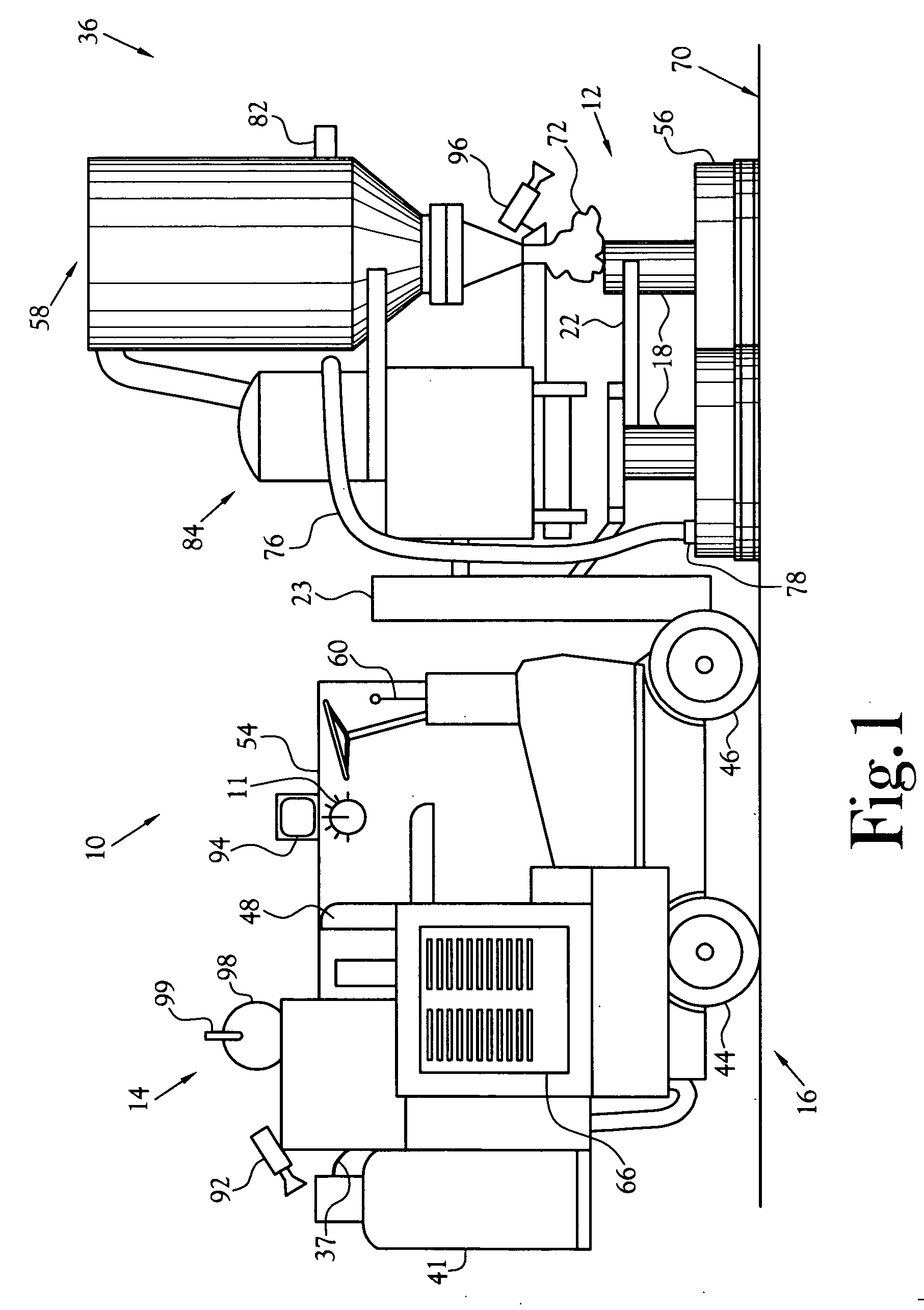
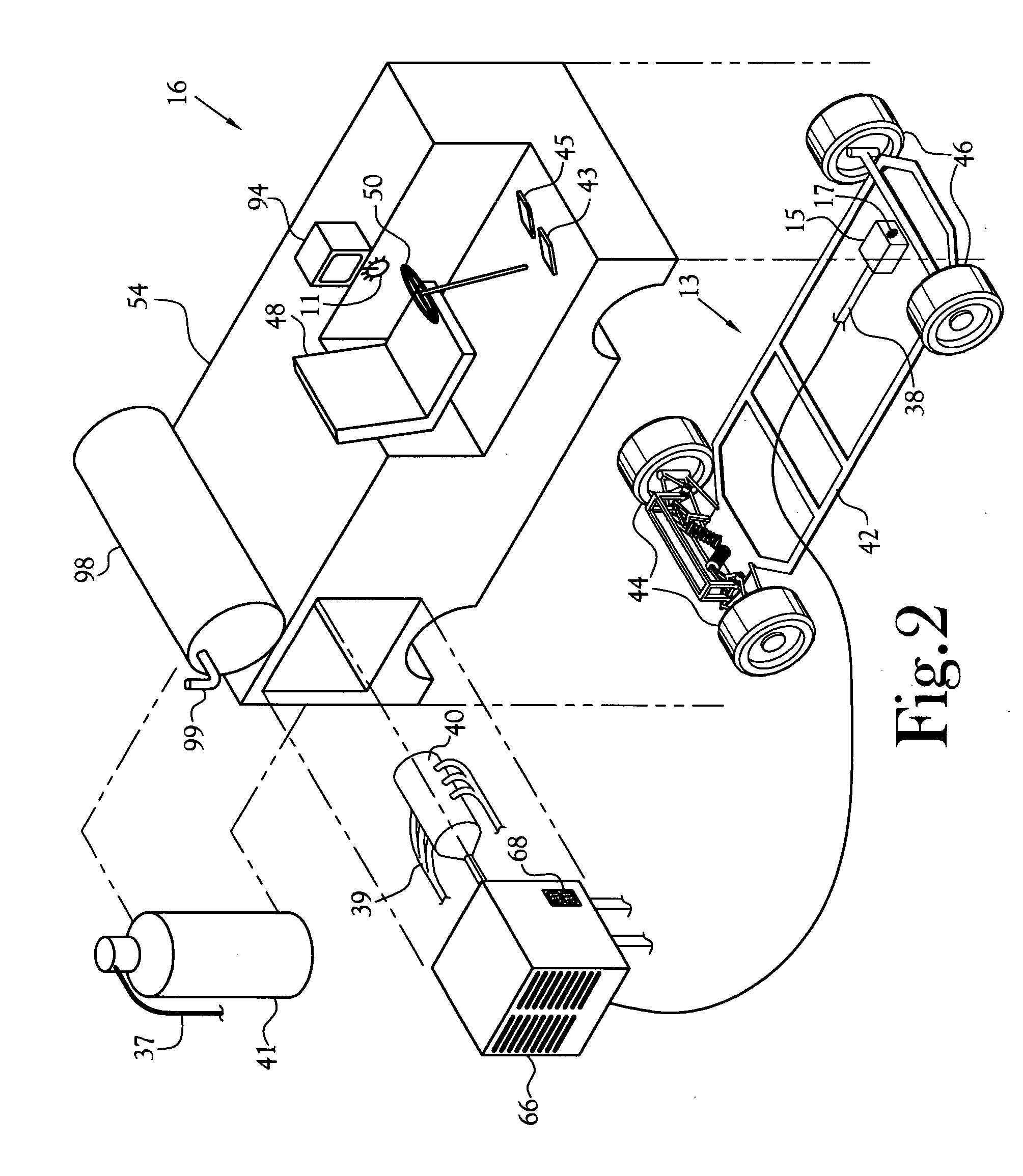
[0030]FIG. 1 is a side view of one embodiment of a riding floor polishing machine 10 constructed in accordance with several features of the present invention. The riding floor polishing machine 10 includes generally a grinder assembly 12 and a dust collection device 36, both carried by a vehicle 16. The grinder assembly 12 includes a plurality of planetary polishing heads 18 carried by a frame 20. The frame 20 is movably attached to the vehicle 16 such that the planetary polishing heads 18 can be moved in either lateral or vertical directions proximate the vehicle 16. As discussed in greater deta...


PUM


Abstract

A riding floor polishing machine with dust and exhaust filtering apparatus is disclosed. The riding floor polishing machine provides a vehicle-driven surface processing apparatus capable of performing a large scale surface polishing operation in an indoor setting with reduced dust accumulation and reduced exhaust emission to the working environment. The riding floor polishing machine includes generally a grinder assembly, an exhaust control device, and a dust collection device, each carried by a vehicle. The grinder assembly includes a plurality of planetary polishing heads carried by a frame. The frame is movably attached to the vehicle such that the planetary polishing heads can be moved in either lateral or vertical directions proximate the vehicle. The vehicle provides mobility to the riding floor polishing machine and includes a power source to provide power for operating the various functions of the grinder assembly, the exhaust control device, and the dust collection device.

Description

CROSS-REFERENCE TO RELATED APPLICATIONS [0001] Not Applicable STATEMENT REGARDING FEDERALLY SPONSORED RESEARCH OR DEVELOPMENT [0002] Not Applicable BACKGROUND OF THE INVENTION [0003] 1. Field of Invention [0004] This invention pertains to surface polishing machines. More particularly, this invention pertains to a riding surface polishing vehicle for conducting various surface polishing operations such as scrubbing, buffing, grinding, or other polishing of floor surfaces or similar, essentially continuous surfaces. [0005] 2. Description of the Related Art [0006] It is often necessary to grind, polish, or otherwise refinish large areas of flooring surface, such as basketball gyms, warehouses, or other such structures. The conventional tool used in performing this type of surface polishing is a hand operated polishing machine. This type of machine typically utilizes surface processing apparatus including at least one planetary frictional surface rotated by an electric motor, a combusti...

Claims


Application Information

Patent Timeline
IPC IPC(8): B24B51/00B24B49/00B24B23/00
CPCA47L11/202A47L11/40B24B55/06B24B7/186B24B49/12A47L11/4061
Inventor PADGETT, STEPHEN DAVIDLIVELY, THOMAS ROY
Owner CAREX POWER TECH
Why Eureka
Try Eureka