Heavy oil hydroconversion process

a technology of heavy oil hydroconversion and hydroconversion reactor, which is applied in the direction of combustion type, effluent separation, and combustion using lump and pulverulent fuel, etc. it can solve the problems of heavy oil hydrocracker concept, unable to meet the requirements of more severe cracking conditions, and no commercially attractive approach has been identified to produce or regenerate hydrogen donor diluent feed, etc., to achieve the effect of facilitating hydrogen transfer and reducing the volume of the step d

Inactive Publication Date: 2007-07-12
BOC GRP INC
View PDF45 Cites 48 Cited by
  • Summary
  • Abstract
  • Description
  • Claims
  • Application Information

AI Technical Summary

Benefits of technology

[0035]In step d, the residence time would typically range between 0.01 and 100 seconds. The pressure during step d is between about 5 and 1000 psig. The use of a residual oil hydrogen donor solvent, rather than the conventional distillate hydrogen donor diluent, decreases the step d minimum pressure and hydrogen donor cracking reactor volume and eliminates the requirement to recycle a distillate hydrogen donor diluent precursor. The colloidal catalyst that is added to step a is entrained with the liquid product from step c and facilitates hydrogen transfer in the step d hydrogen donor cracking process.
[0040](d) providing sufficient residence time to achieve the desired conversion of resid to distillates, and

Problems solved by technology

More severe cracking conditions are not possible because of excessive coke precursor and coke formation.
Although, remarkably efficient heavy oil hydrogen donor diluent cracking processes have been developed over time, no commercially attractive approach has been identified to produce or regenerate the hydrogen donor diluent feed.
However, this design also had a major disadvantage: only the feed oil was available to expand the catalyst bed, which required using either inconveniently large reactor height to diameter ratio or small and difficult to separate catalyst particles.
However, the heavy oil hydrocracker concept also has a significant problem: The resid thermal cracking reactions (Reaction 1 on FIG. 1) must operate at the same temperature as the hydrogenation (Reactions 5 and 7 on FIG. 1) and the free radical termination reactions (Reaction 2 and 6 on FIG. 1).
Unfortunately, the actual hydrogenation reaction rate to thermal cracking reaction rate ratio decreases more rapidly than the required ratio to maintain reactor operability (U.S. Pat. No. 4,427,535).
Clearly, both the heavy oil hydrogen donor diluent cracking (HDDC) and hydrocracker processes have been subject to intensive and innovative development programs.
However, this extensive effort has failed to find a commercially attractive approach to produce the hydrogen donor diluent or thermal crack the heavy oil under optimum conditions.

Method used


Image

  • Heavy oil hydroconversion process
  • Heavy oil hydroconversion process
  • Heavy oil hydroconversion process

Examples


Embodiment Construction

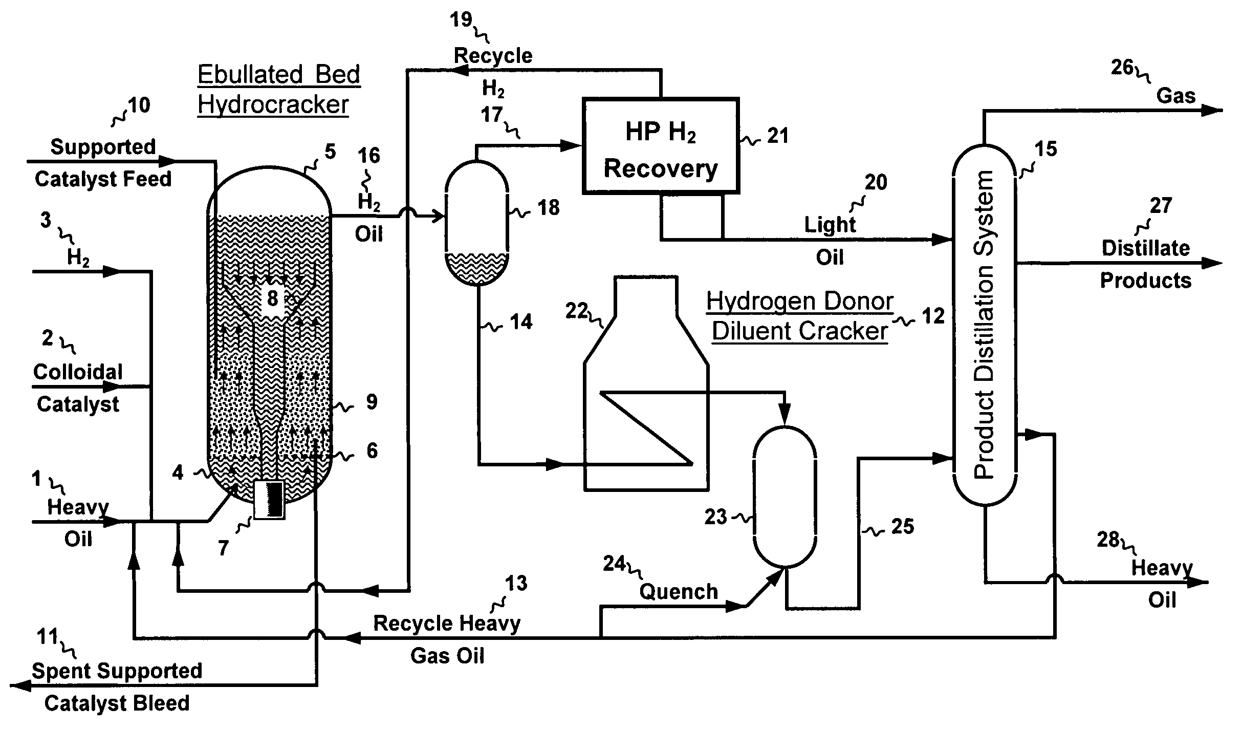
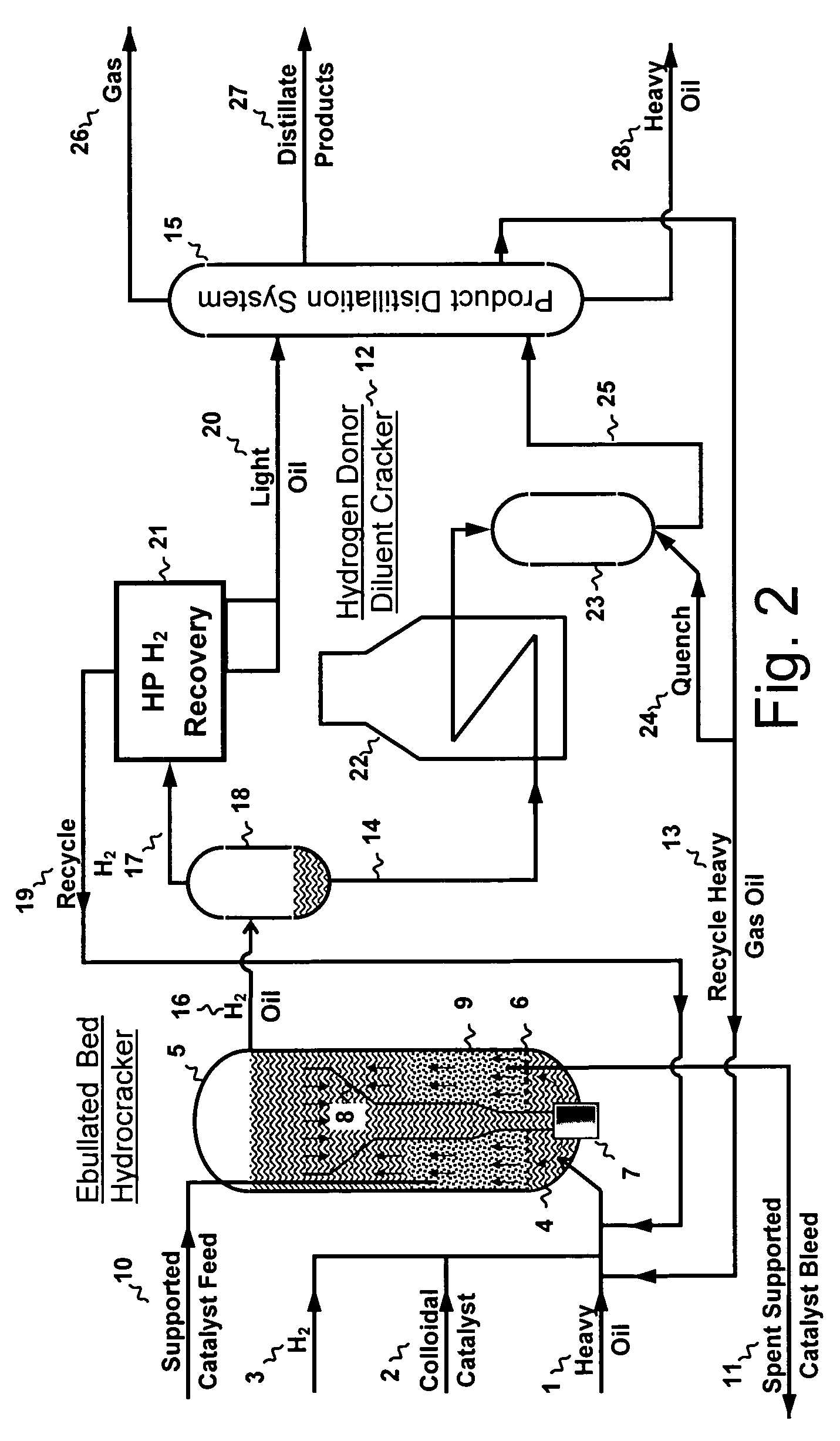
[0051]The process combining heavy oil hydrocracking or hydrotreating and hydrogen donor conversion process will be described with the aid of FIG. 2. The feed heavy oil feed 1 is typically a vacuum resid with an initial boiling normal boiling point of about 975° F. (524° C.). The heavy oil feed typically contains between 5 and 40 weight percent asphaltenes and typically has a Ramsbottom carbon residue analysis value between 10 and 40 weight percent. Typically, between 0.01% and 1% of colloidal molybdenum sulfide catalyst 2 is added to the heavy oil feed 1 to primarily increase the hydrogenation of the asphaltene fraction. The hydrogen feed 3 is typically between 2 and 4 times the anticipated hydrogen consumption. Heavy oil 1, colloidal catalyst 2, and hydrogen 3 are fed into the plenum 4 of ebullated bed hydrocracker reactor 5 below the feed distributor 6. Recycle heavy oil is pumped 7 from the reactor down-corner 8 and is mixed with the heavy oil 1, colloidal catalyst 2, and hydroge...


PUM

PropertyMeasurementUnit
temperatureaaaaaaaaaa
hydrogen partial pressureaaaaaaaaaa

Abstract

A method for the efficient conversion of heavy oil to distillates using sequential hydrocracking in the presence of both supported and colloidal catalyst immediately followed by a high temperature-short residence time thermal treatment. The hydrocracker reaction products or a heavy oil and hydrogen donor diluent may be advantageously heated by direct contact with high velocity combustion products.

Description

BACKGROUND OF INVENTION[0001]The present invention relates to a method for the production and use of hydrogen donor solvents to increase heavy oil-to-hydrocarbon distillate conversion efficiency.[0002]Terminology is important, especially for a complex field like hydrocarbon processing that progressed in parallel and very non-linear scientific and engineering practice pathways. Originally, heavy oils were hydrocarbons with a high density for a given boiling point range. However, the term heavy oil is often used interchangeably with high boiling by practicing engineers because most oil fractions with higher densities also have higher boiling points. However, some highly paraffinic oils or oil fractions may have significantly higher boiling points than much heavier, i.e., denser, aromatic oils or oil fractions. For the purposes of this invention, a heavy oil contains a significant quantity of a high density vacuum residual oil. Residual oils, also called residua or resids, are typicall...

Claims


Application Information

Patent Timeline
Patent Type & Authority Applications(United States)
IPC IPC(8): C10G11/00
CPCC10G65/10C10G47/34
Inventor SATCHELL, DONALD P.
Owner BOC GRP INC
Why Eureka
Try Eureka