
Remote sensor with modular bus adapter

a modular bus and sensor technology, applied in the field of remote sensing with modular bus adapters, can solve the problems of inability to offer the sensing capability the inability to monitor the remote monitoring application of these sensors, and the inability to meet the data collection tasks of many parameters of interest, etc., to achieve the maximum flexibility in network connectivity and topology capabilities, the effect of maximizing system control flexibility and architectural flexibility

Inactive Publication Date: 2007-07-12
RES ANALYSIS & ENG
View PDF4 Cites 22 Cited by
  • Summary
  • Abstract
  • Description
  • Claims
  • Application Information

AI Technical Summary

Benefits of technology

[0016] It is a further object of the present invention provide a remote sensing system and methodology which offers a high degree of flexibility, scalability and connectivity when and as deployed.
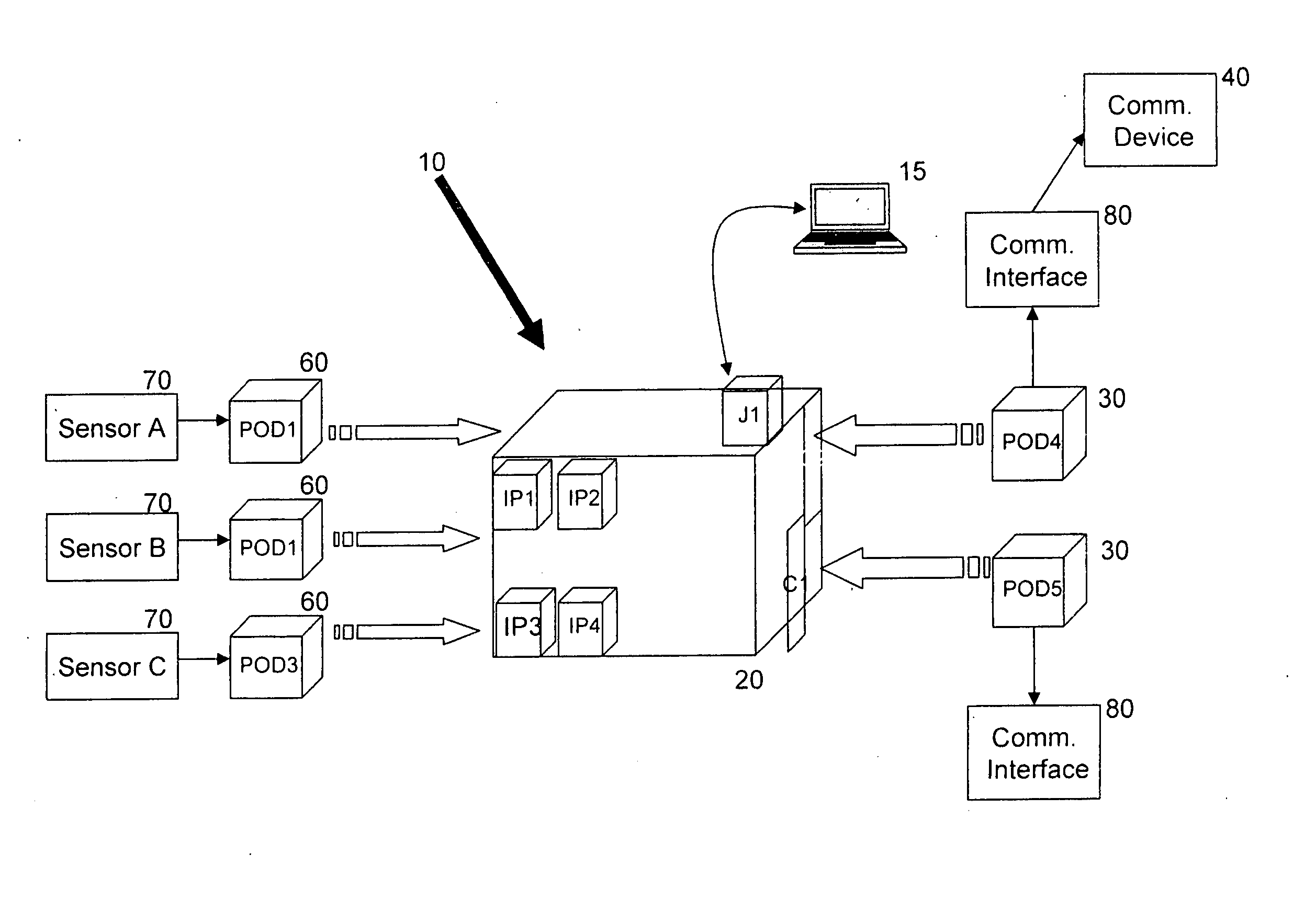
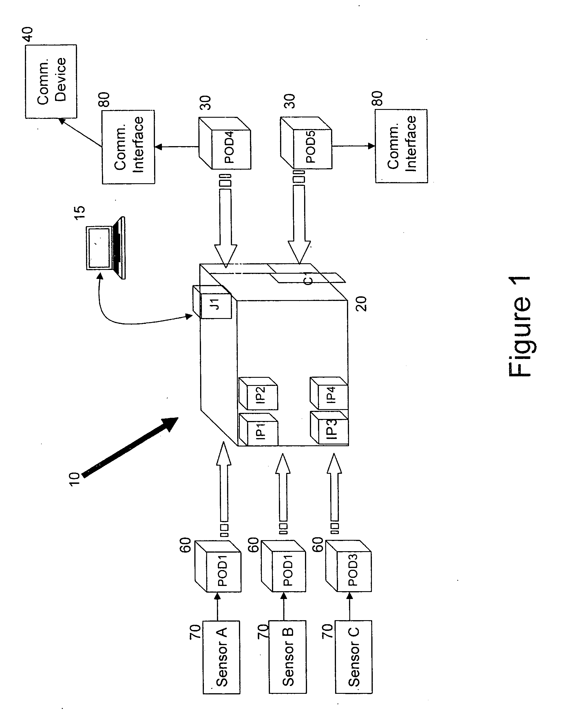
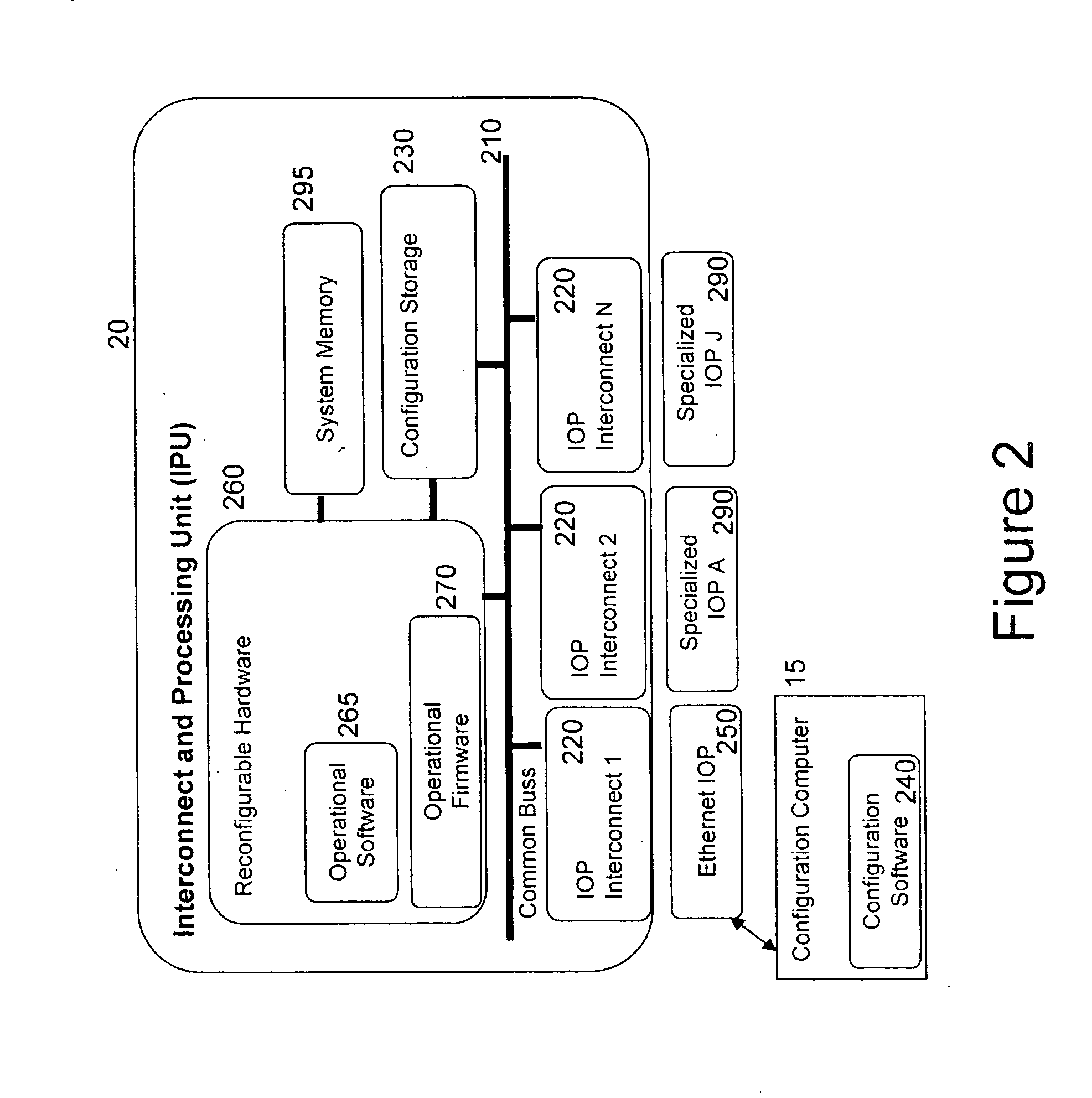
[0024] Modular software running on the system enables functions such as sensor control, signal processing, detection processing, decision logic, alert generation, activity scheduling, data encryption and encoding, tamper protection, and temporary and long term data storage. Given these advantages, a short development time for new sensor and communications component interfaces allows users to maintain operational capability across a range of evolving and presently unanticipated missions.

Problems solved by technology

While discrete in situ and short range standoff sensors are capable of capturing the required data using specialized purpose-built systems and are relatively easily operated, remote monitoring applications of these sensors present more challenging data gathering tasks.
For example, standoff sensing (e.g., optical, infrared, radar) applications from air or space platforms can not offer sensing capability for many parameters of interest, such as vibration and acoustics, chemical agent plumes, air or waterborne biologics, optical or infrared signatures from building interiors or beneath structures (e.g., overpasses), magnetic signatures and the like.
Remote sensing applications as currently practiced also provide additional difficulties.
Current unattended sensing systems are generally “specialty purpose-built.” That is, they are designed to provide high value monitoring with regard to a small number of physical characteristics (e.g., weight or volume), but do so at the expense of offering limited flexibility and limited performance in monitoring or capturing other parameters.
Such systems often cannot be effectively used in environments or for missions other than those for which they were specifically designed.
Additionally, as the component technologies improve, these systems cannot exploit the applicable advances except through a substantial redesign and redeployment.
This can often provide too costly or time consuming to warrant the change.
Yet another limitation of existing purpose-built systems for remote sensing applications is that they usually have sensors and communications devices integrated into a single package.
Although this can optimize a characteristic such as package volume, the resulting system and in-place sensing technology can not be used for applications that call for a different communications device (e.g., greater range, different frequency, alternative operational protocols).
Because of incompatibilities with alternate devices, it is necessary to replace the entire system with a different purpose built system if an alternate communications device is required.
Another disadvantage of most existing remote sensing systems is that interconnecting heterogeneous sensors into a system requires several proprietary components from different vendors.
Still further, connecting a single input into multiple output networks requires special system hardware / software / firmware, which cannot be easily reconfigured.
In addition to the aforementioned drawbacks, existing remote sensing system designs also suffer from limited scalability.
In other words, with these fixed size units, the ability to provide additional sensor connectivity is limited or unavailable.
Further, given the limited sizing of these units, as sensing needs increase or become more varied, the needs can often not be accommodated due to limitations in network connectivity and topology capabilities.

Method used


Image

  • Remote sensor with modular bus adapter
  • Remote sensor with modular bus adapter
  • Remote sensor with modular bus adapter

Examples


Embodiment Construction

[0034] The present invention for a remote sensing system and methodology is now described generally with additional details following the general description now provided.

[0035] The present invention comprises a remote sensing system which includes an Interconnect and Processing Unit (IPU) which functions as an interface between sensors and communications components. The present invention further comprises a process for sensing according to the teachings herein. In the description that follows, numerous specific details are set forth for the purposes of explanation. It will, however, be understood by one of skill in the art that the invention is not limited thereto and that the invention can be practiced without such specific details and / or substitutes therefor. The present invention is limited only by the appended claims and may include various other embodiments which are not particularly described herein but which remain within the scope and spirit of the present invention.

[0036...


PUM


Abstract

A remote sensing system having a modular bus architecture. The bus architecture of the present invention comprises a modular reconfigurable processing unit which functions as an interface between the sensors and the communications components. The system has three main components: (1) input pods that provide physical and logical interfaces to whatever sensors (similar or dissimilar) are to be used, (2) output pods that provide physical and logical interfaces to whatever communications devices (similar or dissimilar) are to be used, and (3) a reconfigurable interface and processing unit that accepts both the input and output pods as plug-in devices and that provides control, format conversion, data buffering, data manipulation, power management, and other needed services for inputting the data, processing the data, and transmitting the data, regardless of the sensor type or communications device.

Description

BACKGROUND [0001] 1. Field of the Invention [0002] The present invention relates generally to sensor and communication systems, and more particularly to unattended sensing systems and the components and architecture thereof. [0003] 2. Background of the Invention [0004] For quite some time, governments have used both active and passive detection systems to remotely track and detect various conditions, persons and physical objects. Intelligence applications include the use of satellite-based sensors including high-resolution cameras, infrared, and radio direction finding equipment, as well as locally placed sensors to detect acoustic, magnetic and other physical properties to covertly monitor areas of interest. Only recently have economies of scale and new manufacturing efficiencies and techniques permitted using derivatives of these technologies for commercial applications. [0005] Given today's geo-political climate and the increasing need to monitor various activities, facilities an...

Claims


Application Information

Patent Timeline
IPC IPC(8): G06F13/38
CPCG06F13/387
Inventor MARTIN, WAYNE W.WILLIAMS, GILBERT T.
Owner RES ANALYSIS & ENG
Learn More