Lubricant supply system and operating method of multisystem lubrication screw compressor

a screw compressor and lubricant supply technology, which is applied in the direction of machines/engines, rotary/oscillating piston pump components, liquid fuel engines, etc., can solve the problems of reducing the life of bearings, reducing the strength of bearing materials, and no bearing material superior than white metal has been commercially available as of now, so as to prevent the abnormal rise of pressure in the bearing lubricating oil supply system

Active Publication Date: 2007-07-19
MAYEKAWA MFG CO LTD
View PDF5 Cites 25 Cited by
  • Summary
  • Abstract
  • Description
  • Claims
  • Application Information

AI Technical Summary

Benefits of technology

[0010] The present invention was made in light of aforementioned problems, and an object of the invention is to provide a lubricant supply system of a screw compressor and operating method thereof, with which reduction in strength of the rotor bearings, occurrence of bearing seizure, and reduction in wear resistance of the bearings can be prevented and bearing life is prolonged without reducing overall performance of the screw compressor.
[0011] Another object of the invention is to provide a lubricant supply system, with which the lube oil flow for lubricating the rotor bearings can be minimized, discharge gas temperature compressed by the compressor can be maintained at high temperature, and lube oil for lubricating the bearings can be supplied in a temperature lower than a permissible temperature for the bearings, which enables adoption of low viscosity oil.
[0012] A further object of the invention is to provide a lubricant supply system, with which constituent devices such as oil separator can be small sized, separation efficiency of the oil separator can be increased, and intrusion of foreign matter contained in fluid to be compressed into lube oil can be minimized.

Problems solved by technology

However, operation of the compressor under high temperature causes reduction in strength of bearing material due to heat generation by sliding in rotor bearings or reduction of lifetime of bearings due to lowering in viscosity of lube oil.
To solve the problem, it is demanded to develop bearing material of high heat tolerance, but no bearing material superior than white metal has been commercially available as of now as far as economical efficiency and reliability are concerned.
Further, synthetic lube oil has hydrophilic property, and when water or active ingredient was contained in fluid f to be compressed, hydrolysis cleavage or corrosion of bearing material occurred.
However, in a screw compressor used in a refrigerating system or compression system using as a refrigerant a highly soluble gas which is highly soluble in lube oil, such as high condensable gas having relatively high boiling point, wear resistance of bearings deteriorates rapidly when lube oil temperature exceeds 125° C., and operating life of the compressor is shortened.
Abovementioned material of lubricating part does not necessarily provide a lubricating part superior in wear resistance under high temperature.
Further, when aluminum alloy or silver is adopted as bearing material, running-in property is not good and bearing seizure is apt to occur.
However, there is a restriction to increasing temperature that, when the temperature of lube oil is raised, occurrence of bearing seizure and reduction of bearing life are induced.
As to pressure, there is a restriction that pressure of lube oil injected into the rotor room must be high than a certain pressure, for when supply pressure of lube oil to the balance piston to reduce thrust force exerting on the male rotor from discharge side toward suction side, the thrust load of the thrust bearing increases resulting in reduced life of the thrust bearing.

Method used


Image

  • Lubricant supply system and operating method of multisystem lubrication screw compressor
  • Lubricant supply system and operating method of multisystem lubrication screw compressor
  • Lubricant supply system and operating method of multisystem lubrication screw compressor

Examples


first embodiment

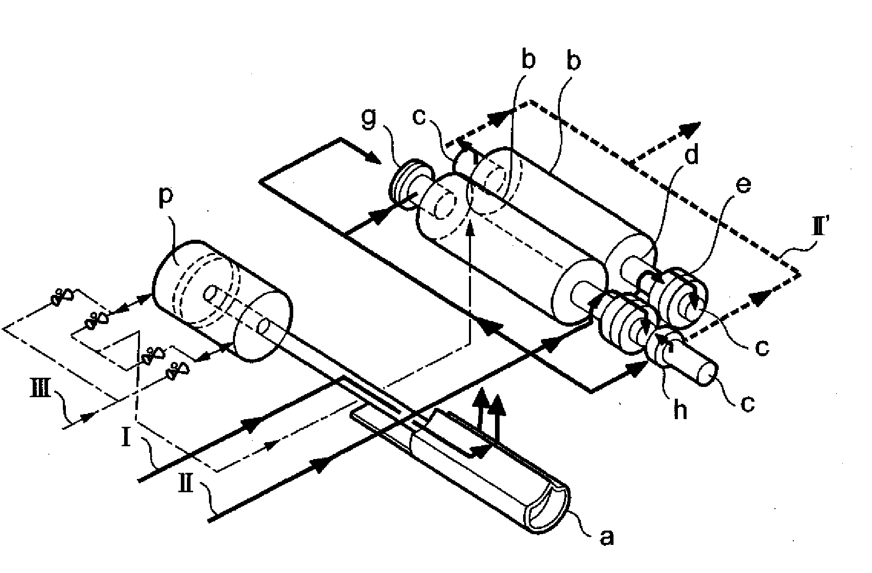
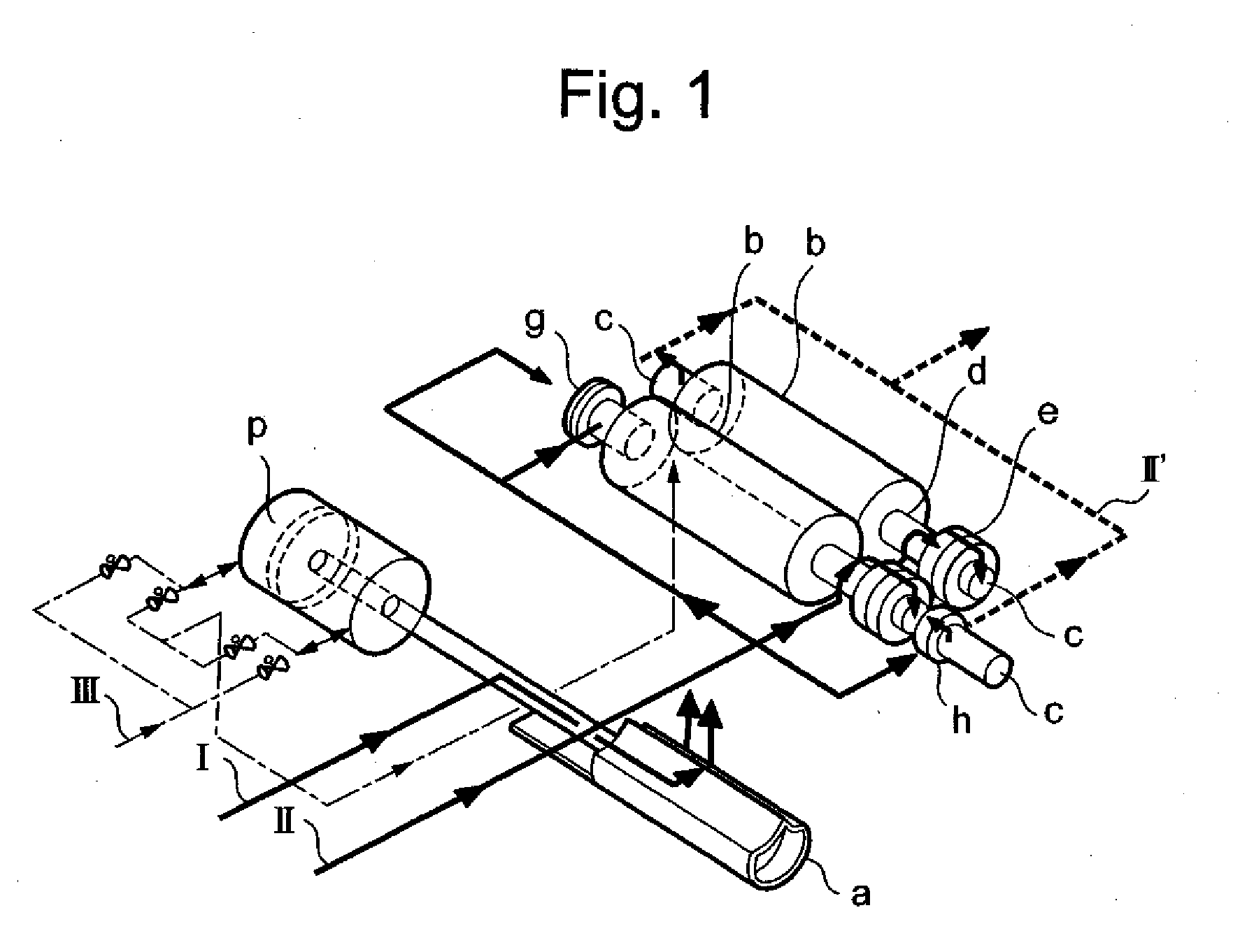
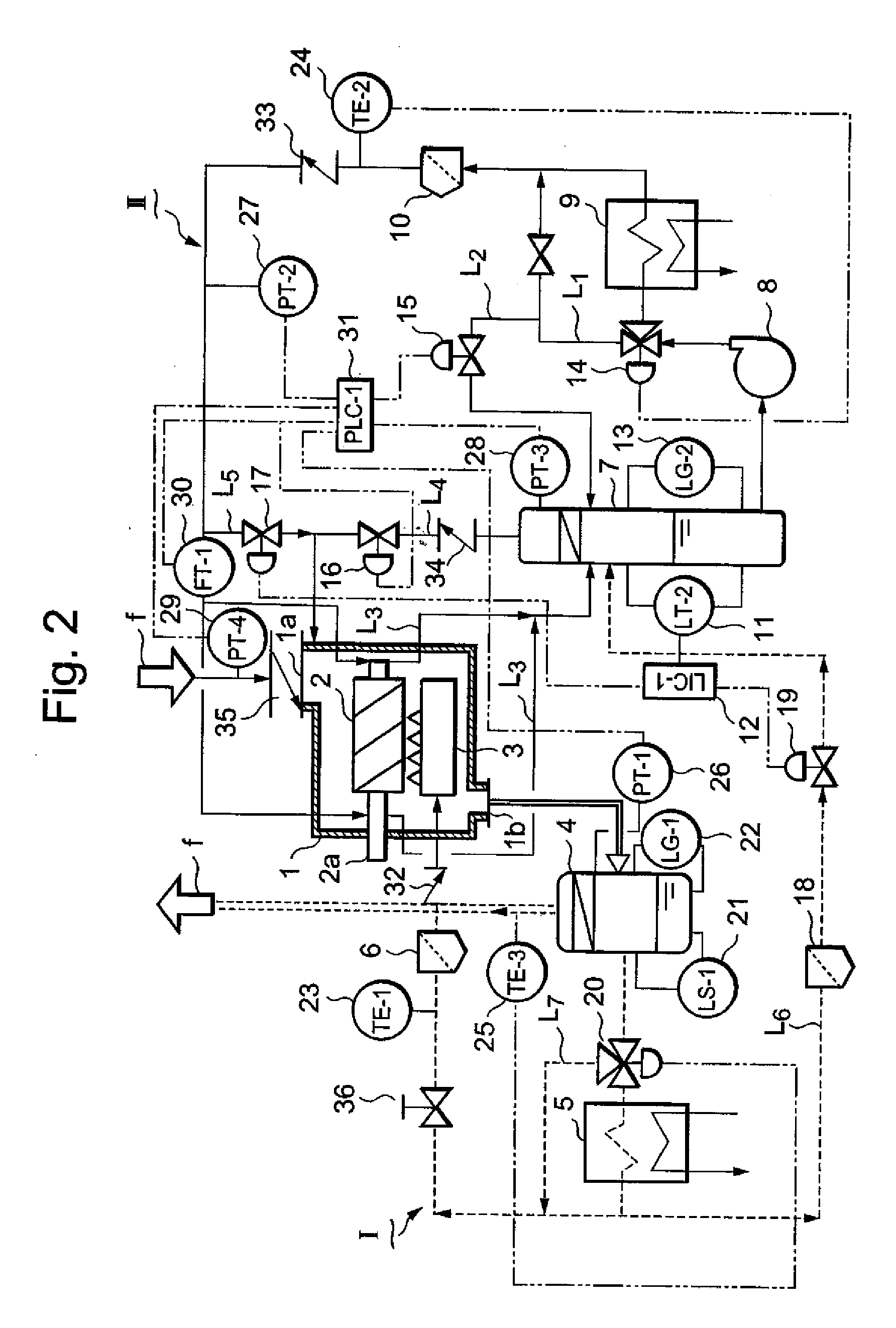
[0053] Next, in FIG. 2 showing the lube oil supply system of the invention, reference numeral 1 is a screw compressor, 2 is a screw rotor of a pair of male and female screw rotors supported rotatably in the rotor casing of the compressor 1, 3 is a slide valve for injecting lube oil to the rotor 2 in the rotor casing. Reference numeral 1a is a suction port of fluid f to be compressed, 1b is a discharge port of compressed fluid f, and 2a is a shaft part of the rotor 2.

[0054] The fluid f to be compressed is sucked from the suction port 1a into the compressor 1 and compressed as the rotors 2 rotate to be discharged in a pressurized state together with lube oil mixed in it. The mixed lube oil is separated from the compressed gas in an oil separator 4. The separated lube oil is cooled in an oil cooler 5, filtered through a filter 6 to remove foreign matter, and again returned to the slide valve 3. This closed circulation circuit composes the temperature control, oil supply line I and show...

second embodiment

[0082]FIG. 4 is a partial block diagram of lube oil supply system of screw compressor according to the present invention. In FIG. 4, the same instruments and parts as sown in FIG. 2 and FIG. 3 are indicated by the same reference numerals.

[0083] In FIG. 4, a path L8 is an oil supply path branching from the bearing lubricating oil supply line II in order to supply oil to a balance piston 51, reference numeral 52 and 53 are respectively a flow regulator valve and a flow detector for detecting flow rates and transmitting signals of detected flow rates provided to the bearing lubricating oil supply line II. Construction except those instruments and parts that are added is the same as that of the first embodiment.

[0084] In the second embodiment, oil to be supplied to the balance piston 51 and oil to be supplied to bearings and oil seals are pressurized by the oil supply pump 8, and the pressurized oil supply is divided in two lines so that high-pressure oil is supplied to the balance pis...


PUM


Abstract

An oil refrigeration screw compressor being applied to a refrigeration system etc., in which the problem of strength reduction of a bearing material under high temperatures and that of lifetime reduction of the bearing material due to viscosity lowering of lubricant are solved. A lubricant supply system to a compressor body is divided into a bearing oil supply system for supplying lubricant to each bearing of the compressor body at low pressure and into a temperature control oil supply system for supplying lubricant into the compressor body at high pressure. The bearing oil supply system is a closed circuit oil supply system comprising an oil supply tank, an oil cooler, and an oil supply pump, and the temperature control oil supply system is a closed circuit oil supply system comprising an oil separator and an oil cooler.

Description

[0001] This is a continuation of International Application PCT / JP2004 / 011412 (published as WO 2006 / 013636) having an international filing date of 03 Aug. 2004, the contents of which is incorporated by reference herein.TECHNICAL FIELD [0002] The present invention relates to a lubricant supply system of a screw compressor having multi-lubricating system with which problems of reduction in strength of bearing material under high temperature and reduction in lifetime of the bearing material due to lowering in viscosity of lube oil through separating the lube oil supply system to the compressor into an injection-supply line for supplying lube oil to the rotors of the compressor and a supply line for supplying lube oil to the bearings of the compressor, in an oil-cooled screw compressor, for example, used for refrigerating system, and an operating method of the compressor. BACKGROUND ART [0003] Previously, an oil-cooled screw compressor was composed such that, lube oil supplied through an...

Claims


Application Information

Patent Timeline
Patent Type & Authority Applications(United States)
IPC IPC(8): F01M1/00
CPCF04C18/16F04C29/02F04C29/021F04C2240/56F04C29/026F04C29/042F04C29/025
Inventor SEKIYA, YOSHIMITSUTANAKA, KIYOSHIFUKANO, SHUJINAKAI, HIRONORIKUBOTA, YOSHIFUSASHOZU, TEIJI
Owner MAYEKAWA MFG CO LTD
Why Eureka
Try Eureka