Transport robot and transport apparatus

a technology of transport robots and transport apparatus, which is applied in the field of transport robots, can solve the problems of high cost, inconvenient use of solid-lubricated bearings, and accumulation of received data from the substrate, and achieve the effects of reducing maintenance frequency, reducing operational errors, and reducing temperature rise and evaporation

Active Publication Date: 2007-07-19
ULVAC INC
View PDF2 Cites 18 Cited by
  • Summary
  • Abstract
  • Description
  • Claims
  • Application Information

AI Technical Summary

Benefits of technology

[0049] In a transport robot of the present invention, even when thermal energy flows into the transport robot due to radiation or thermal conduction from a heated substrate, the thermal energy that flows in is released from the release-side high radiation ratio portion, and the released thermal energy is transferred from the receive-side high radiation ratio portion to the vacuum chamber; and consequently, thermal energy is not accumulated in the transport robot. Accordingly, even when the arm of the transport robot is placed in a vacuum atmosphere, it is possible to suppress temperature rising and evaporation of lubrication oil used for bearings of the transport robot. As a result, the transport robot of the present invention suffers less operational errors, which reduces frequency of maintenance work. Also, since the arm temperature of the transport robot of the present invention is kept low, the effect of extension of the arm due to thermal expansion is small. Therefore, in addition to the fact that the reproducibility of the substrate position when holding the substrate does not deteriorate, the amount of emitted gas released from the robot arm is also small.

Problems solved by technology

In many cases a bearing has a spherical body, a small contact area and a very low thermal conductivity; and therefore, heat received from the substrate accumulates in the arm of the vacuum robot instead of escaping to the vacuum chamber.
Conventional vacuum robots are not suitable for use at a high temperature.
In order to enable such a use at a high temperature, it is required to use a solid-lubricated bearing, which is expensive, to support a support shaft.
As a result, maintenance work is required at short-time intervals or an operation error occurs due to defective lubrication.
However, if an energy amount carried to the outside of the vacuum environment (normally, the atmosphere environment) is small, the vacuum robot eventually reaches a high temperature.

Method used


Image

  • Transport robot and transport apparatus
  • Transport robot and transport apparatus
  • Transport robot and transport apparatus

Examples


Embodiment Construction

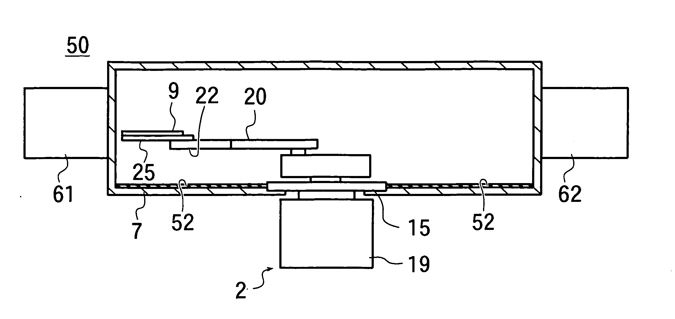
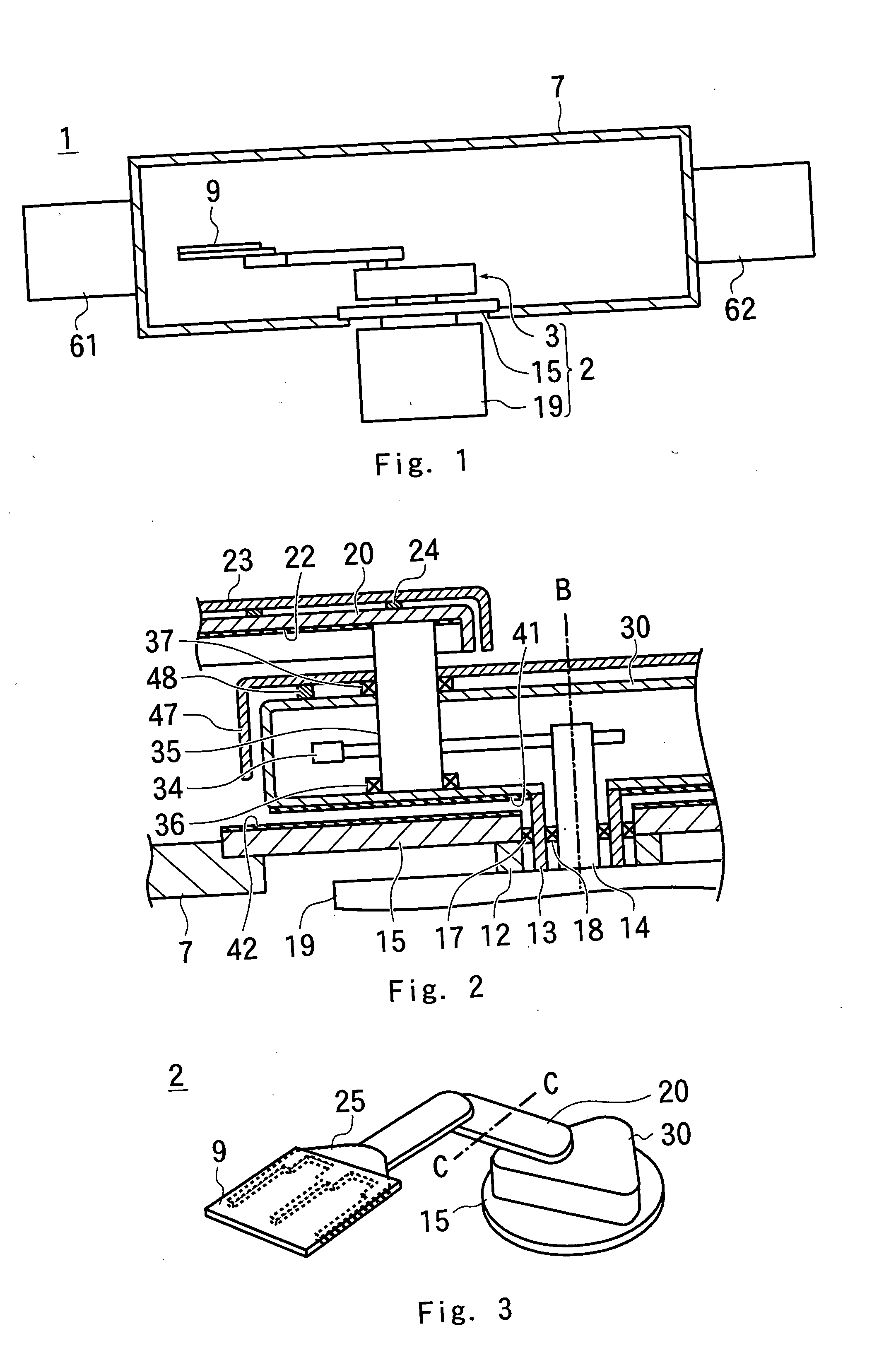
[0058] Reference numeral 1 in FIG. 1 shows an example of a transport apparatus of the present invention, and the transport apparatus 1 has a transport robot 2 and a vacuum chamber 7.

[0059] The transport robot 2 has a plate-shaped base flange 15, a motor portion 19 (driving system) for generating driving force that is located on one surface side of the base flange 15, and a transport system 3 for moving a substrate described below with the driving force generated by the motor portion 19, the transport system 3 being located on the other surface side of the base flange 15.

[0060] A through hole having a smaller diameter than that of the planer shape of the base flange 15 is formed at the bottom wall of the vacuum chamber 7. The transport robot 2 is attached such that the transport system 3 is disposed inside the vacuum chamber 7, and the motor portion 19 is disposed outside the vacuum chamber 7, with the rim portion of the base flange 15 closely contacted with the area around the thr...


PUM


Abstract

A transport robot including a release-side high radiation ratio portion and a receive-side high radiation ratio portion that face each other. Heat in a substrate conducted to a base portion due to thermal conduction is released as radiant heat from the release-side high radiation ratio portion, and the radiant heat is absorbed by the receive-side high radiation ratio portion. The receive-side high radiation ratio portion is formed on a heat-receiving plate that is thermally connected to a vacuum chamber so that radiant heat absorbed by the receive-side high radiation ratio portion is transferred to the vacuum chamber. As a result, even in the case where the high-temperature substrate is transported in a vacuum atmosphere, heat from the substrate is not accumulated in a transport system, and the transport system hardly reaches a high temperature.

Description

CROSS-REFERENCE TO RELATED APPLICATIONS [0001] This application claims priority benefit of Japanese Application No. 2004-357778, filed on Dec. 10, 2004, the entire disclosure of which is incorporated herein by reference. [0002] This application is a continuation of International Application No. PCT / JP2005 / 022616, filed on Dec. 9, 2005, the entire disclosure of which is incorporated herein by reference.BACKGROUND OF THE INVENTION [0003] 1. Field of the Invention [0004] The present invention generally relates to transport robots for transporting objects to be transported in a vacuum atmosphere. [0005] 2. Description of the Related Art [0006] Conventionally, for vacuum apparatuses (such as, film forming apparatuses), a vacuum robot (transport robot) is used capable of transporting a substrate while a vacuum atmosphere is maintained in a vacuum chamber. [0007] The vacuum robot transports unprocessed substrates and processed substrates in the vacuum chamber. A substrate after subjected t...

Claims


Application Information

Patent Timeline
Patent Type & Authority Applications(United States)
IPC IPC(8): H01L21/677
CPCB25J19/0054Y10S700/90Y10S414/139H01L21/68707
Inventor KOIKE, TOSHIO
Owner ULVAC INC
Why Eureka
Try Eureka