Letterpress printing machine

a printing machine and letterpress technology, applied in printing presses, office printing, printing, etc., can solve the problems of high manufacturing cost, ink accumulation, high manufacturing cost, etc., and achieve the effect of improving the wettability of ink to a relief printing plate, good printing, and improving quality

Active Publication Date: 2007-08-02
TOPPAN PRINTING CO LTD
View PDF11 Cites 8 Cited by
  • Summary
  • Abstract
  • Description
  • Claims
  • Application Information

AI Technical Summary

Benefits of technology

[0116]According to the letterpress printing machine of the present invention, a relief printing plate can be washed without damaging a relief printing plate while a relief printing plate is installed in a printing cylinder.
[0117]Therefore, good printing can be performed right after washing a relief printing plate because wettability of ink to a relief printing plate improves.
[0118]According to the current invention, printing can be performed at constant printing pressure within a printing face. Therefore, when there is undulation in a surface of press plate and a surface of substrate, quality trouble due to printing pressure variation in a printing direction and a direction which i...

Problems solved by technology

In this photo-lithography method, a manufacturing cost is high for reasons of the follows.
2. Manufacturing facility is expensive.
However, while a minute pattern printing is performed consecutively, dry ink accumulates in the surface and concave portions of a relief printing plate.
And defectiveness such as fluctuation of printed line width and printed film thickness occurs.
Therefore, damage to a relief printing plate is big when a relief printing plate having minute pattern is washed regularly in an interval of presswork.
Therefore, good printing cannot be performed.
In addition, a relief printing plate is hard to get used to ink after having done cleaning of a relief printing plate.
Therefore, enough inking is unable.
Therefore, defectiveness such as reduction of line width or tackiness in printed matter occurs.
On the occasion of mass production, there is a problem that a large quantity of substrates is used in periodical waste printing.
Therefore, printing pressure is uneven in a printing direction and a direction that is perpendicular to the printing direction.
Therefore, when fine printing is performed, this unevenness aff...

Method used


Image

  • Letterpress printing machine
  • Letterpress printing machine
  • Letterpress printing machine

Examples


embodiment 1

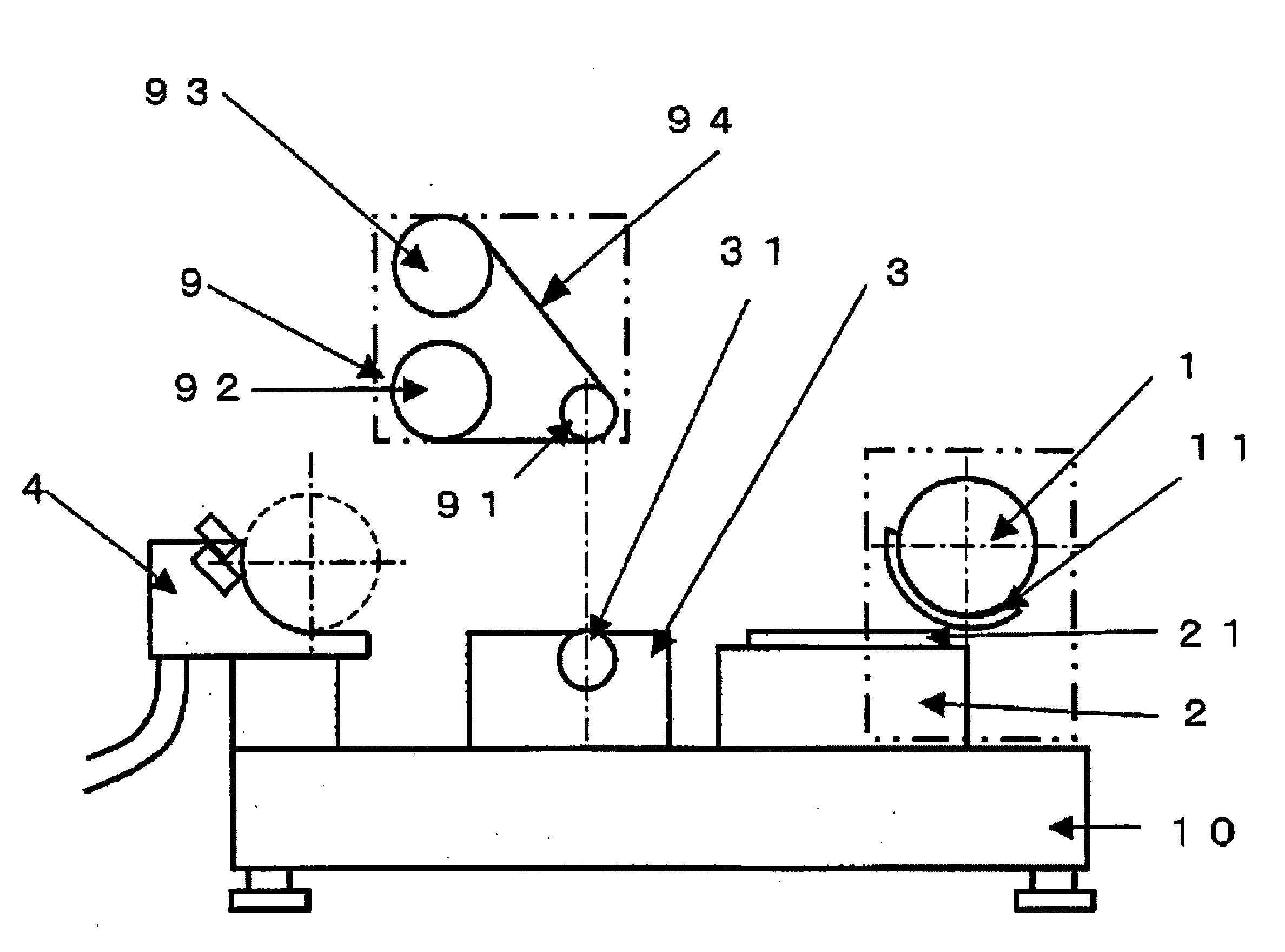
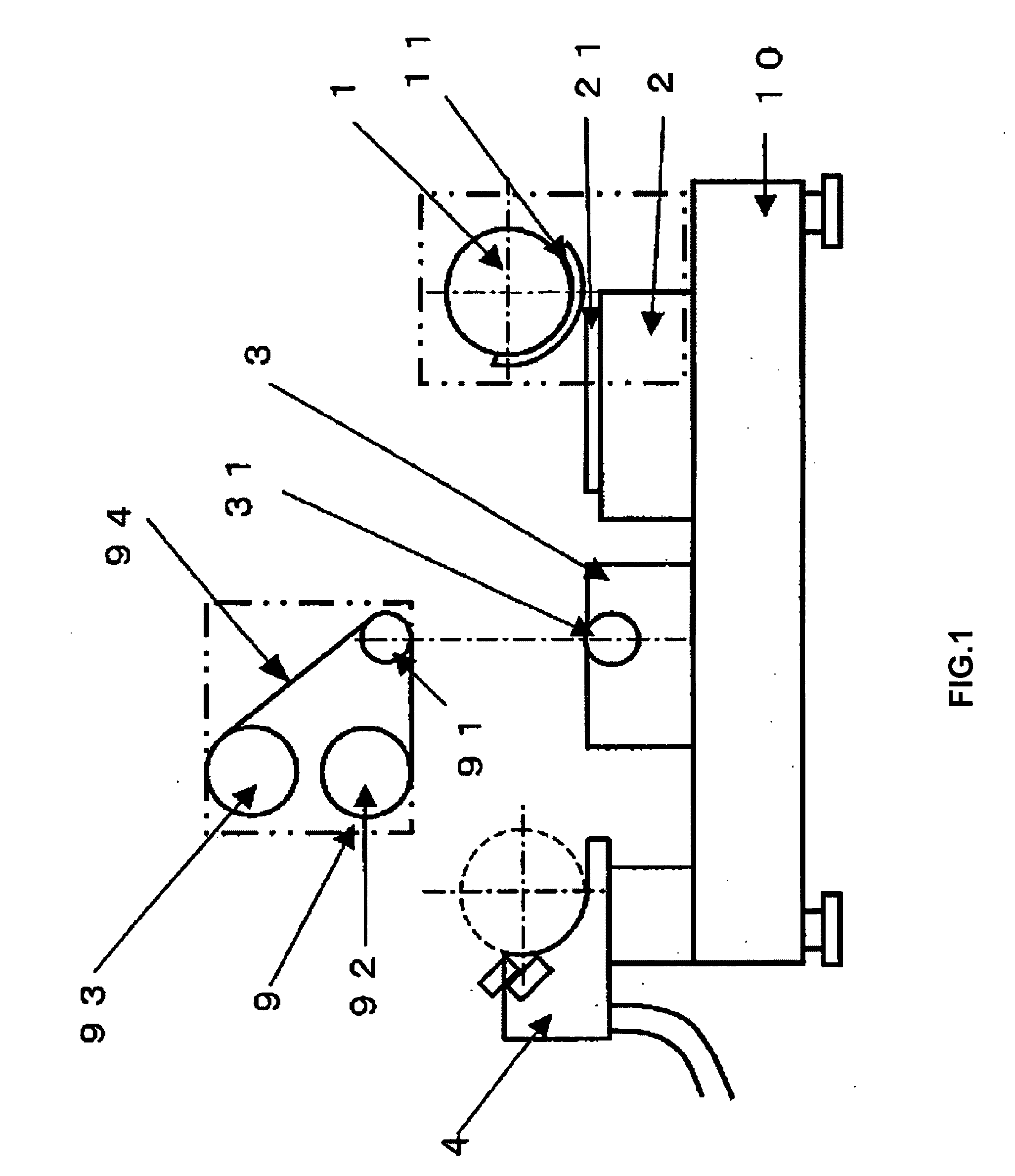
[0068]The present invention is a letterpress printing machine comprising a rotary printing cylinder having a relief printing plate, a substrate surface plate on which a substrate is placed and the ink supply device which applies ink to a relief printing plate. Especially the present invention is applied to a flexographic printer.

[0069]In addition, for an embodiment of a printer, the following embodiments can be adopted: The embodiment that a rotary printing cylinder moves over a substrate surface plate; and the embodiment that a substrate surface plate moves under a printing cylinder.

[0070]In addition, for ink supply device, the following embodiments can be adopted: Plane anilox board comprises a doctoring mechanism; an anilox roll; and a capillary coater.

[0071]In addition, an installation configuration of a relief printing plate washing equipment changes depending on a mechanism of a letterpress printing machine.

[0072]A relief printing plate washing equipment of a letterpress print...

embodiment 2

[0092]A letterpress printing machine of the present invention has a mechanism to keep a fixed printing pressure within a printing face. A mechanism to keep a fixed printing pressure within a printing face is explained below. The mechanism senses change of printing pressure between a relief printing plate placed on a printing cylinder and a substrate put on a substrate surface plate. And the mechanism moves a substrate surface plate and / or a printing cylinder up and down. Then the mechanism can keep a fixed printing pressure within a printing face.

[0093]For such a mechanism, a pneumatic actuator, an air cylinder, a hydraulic actuator or a hydraulic cylinder can be used. A pneumatic actuator can be handled easily. A hydraulic actuator is powerful and is superior in repeatability. Depending on the weight and the size of a printing cylinder or a substrate surface plate supported by an actuator, a kind of an actuator can be selected.

[0094]In example 2, a letterpress printing machine whic...

embodiment 3

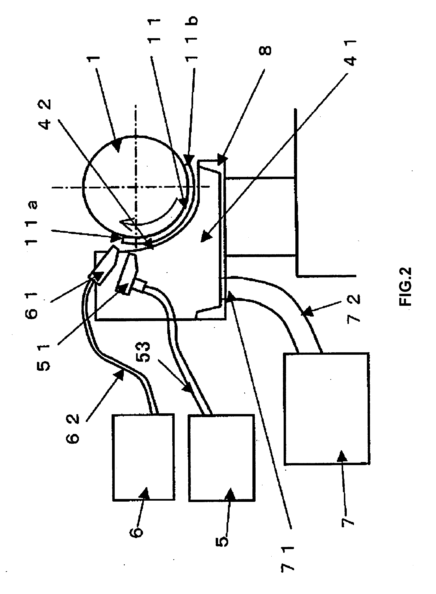
[0095]FIG. 9 is a schematic diagram of an apparatus which a letterpress printing machine of the present invention is applied to a flexographic printer which is suitable for forming luminescent layer of an organic electroluminescent element.

[0096]FIG. 10 is a schematic diagram showing movement of a printer of the present invention at the time of ink transposition.

[0097]A flexographic printer shown in this detailed description of the preferred embodiment has the following member as shown in FIG. 9 and FIG. 10: Rotary printing cylinder 511 supported at a fixed position; Relief printing plate (flexographic plate) 52 for luminescent pattern formation loaded on a surface of printing cylinder 511; Horizontal support base 53 under printing cylinder 511; Surface plate 54 which is placed on support base 53 through guide 53a and which is displaceable horizontally to a direction which is perpendicular to axis of rotation 51a; Substrate 55 put on surface plate 54; Ink supply means 56 supplying i...


PUM


Abstract

A letterpress printing machine is disclosed including a rotary printing cylinder in which a relief printing plate is installed, a substrate surface plate on which a substrate is placed, an ink supply device supplying ink on the relief printing plate, a relief printing plate washing equipment washing the surface of the relief printing plate, and a wiper for a plate. The relief printing plate washing equipment can include a washing liquid supplying unit, an air blasting unit jetting pressurized gas to the relief printing plate, a suction unit sucking the washing liquid scattered by air blasting unit, and a washing liquid recovery unit.

Description

CROSS REFERENCE[0001]This application claims priority to Japanese application number 2006-20478, filed on Jan. 30, 2006, priority to Japanese application number 2006-23335, filed on Jan. 31, 2006, and priority to Japanese application number 2006-121496, filed on Apr. 26, 2006, which are incorporated herein by reference.BACKGROUND OF THE INVENTION[0002]1. Field of the Invention[0003]The present invention is related to a letterpress printing machine. Especially the present invention suits to form a luminescent layer of a macromolecular system organic electroluminescent display unit by printing. In addition, in this case, the ink having a macromolecular system organic material dissolved in a solvent is printed on a substrate.[0004]In addition, the present invention is related to flexographic printing method. In addition, the present invention is related to a letterpress printing machine with the use of a plastic plate. According to the current invention, minute pattern can be formed on...

Claims


Application Information

Patent Timeline
IPC IPC(8): B41F35/00
CPCB41F35/02B41P2235/24B41P2235/30B41P2235/27B41P2235/26
Inventor KONAKA, YUKIOFUKUHARA, TOMOAKIMATSUZAWA, HIROSHI
Owner TOPPAN PRINTING CO LTD
Why Eureka
Try Eureka