Method of generating discharge plasma

a discharge plasma and plasma technology, applied in the direction of electric variable regulation, instruments, manufacturing tools, etc., can solve the problems of difficult to generate and maintain discharge plasma with high electron density and low electron temperature, and achieve the effect of reducing the duty ratio of pulse voltage, reducing the off-time of pulses, and reducing the electron temperature of plasma

Inactive Publication Date: 2007-08-02
NGK INSULATORS LTD
View PDF12 Cites 18 Cited by
  • Summary
  • Abstract
  • Description
  • Claims
  • Application Information

AI Technical Summary

Benefits of technology

[0014] The present inventors have tried to considerably lower the duty ratio of the pulse voltage for generating and maintaining the discharge plasma and increase the off-time of the pulse. It is thus found that the electron temperature of the plasma can be considerably lowered under the condition that the electron density can be maintained at a high value, and the present invention is made.

Problems solved by technology

It is, however, difficult to generate and maintain discharge plasma having a high electron density and a low electron temperature.

Method used


Image

  • Method of generating discharge plasma
  • Method of generating discharge plasma
  • Method of generating discharge plasma

Examples


experiment 1

(Experiment 1)

[0069] The system explained referring to FIG. 3 was used to generate glow discharge and plasma. A chamber 1 was made of stainless steel and substantially had a shape of a disk. The height of the chamber was 300 mm and the diameter φ was 300 mm. The chamber 1 was equipped with a view window 16, a Langmuir probe 17 and an electrode 5 made of stainless steel. The electrode 5 and the chamber 1 were insulated with an insulator 14. The height “D” of the probe was made 60 mm and the diameter “E” of the electrode 5 was made 100 mm. A power source using a static induction thyristor device was used as a power source.

[0070] A rotary pump and a turbo molecular pump were used to evacuate the chamber 1 until the pressure of argon gas in the chamber 1 reached 2.6 Pa. Positive pulses were periodically applied. The positive pulse had a peak value of +10.0 kV and a frequency of 1 to 10 kHz. The half value width of the positive pulse was 1000 nsec. The duty ratio of the pulse voltage wa...

experiment 2

(Experiment 2)

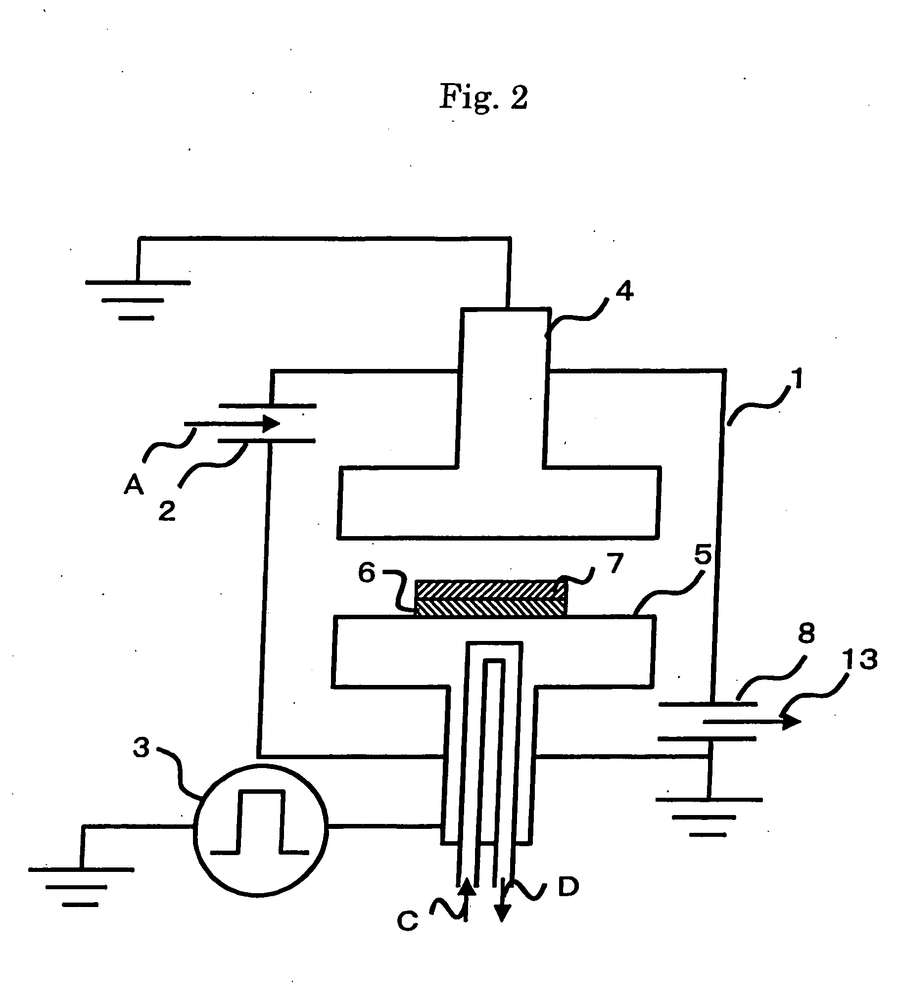
[0074] The system explained referring to FIG. 2 was used to produce a thin film of diamond-like carbon, as described above. A chamber 1 was made of stainless steel and substantially had a shape of a disk. The height of the chamber was 300 mm and the diameter φ was 300 mm. A power source using a static induction thyristor device was used as a power source.

[0075] An rotary pump and an oil diffusion pump were used to evacuate the chamber 1 until a pressure in the chamber 1 reached 1×10⁻² to 1×10⁻³ Pa. Acetylene gas was then supplied into the chamber 1 through a supply hole until the pressure in the chamber reached 2.6 Pa. Pulse voltage was then applied on the upper electrode 4 and the lower electrode 5.

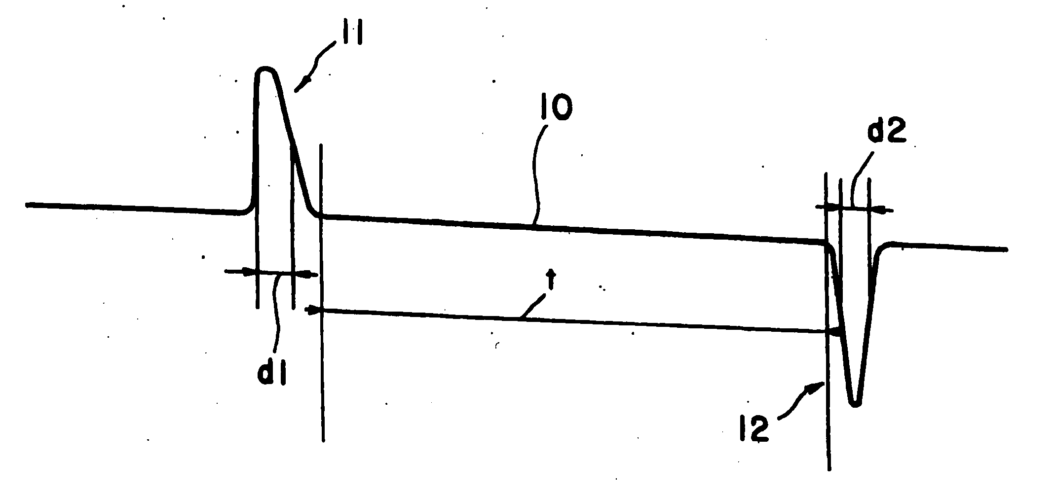
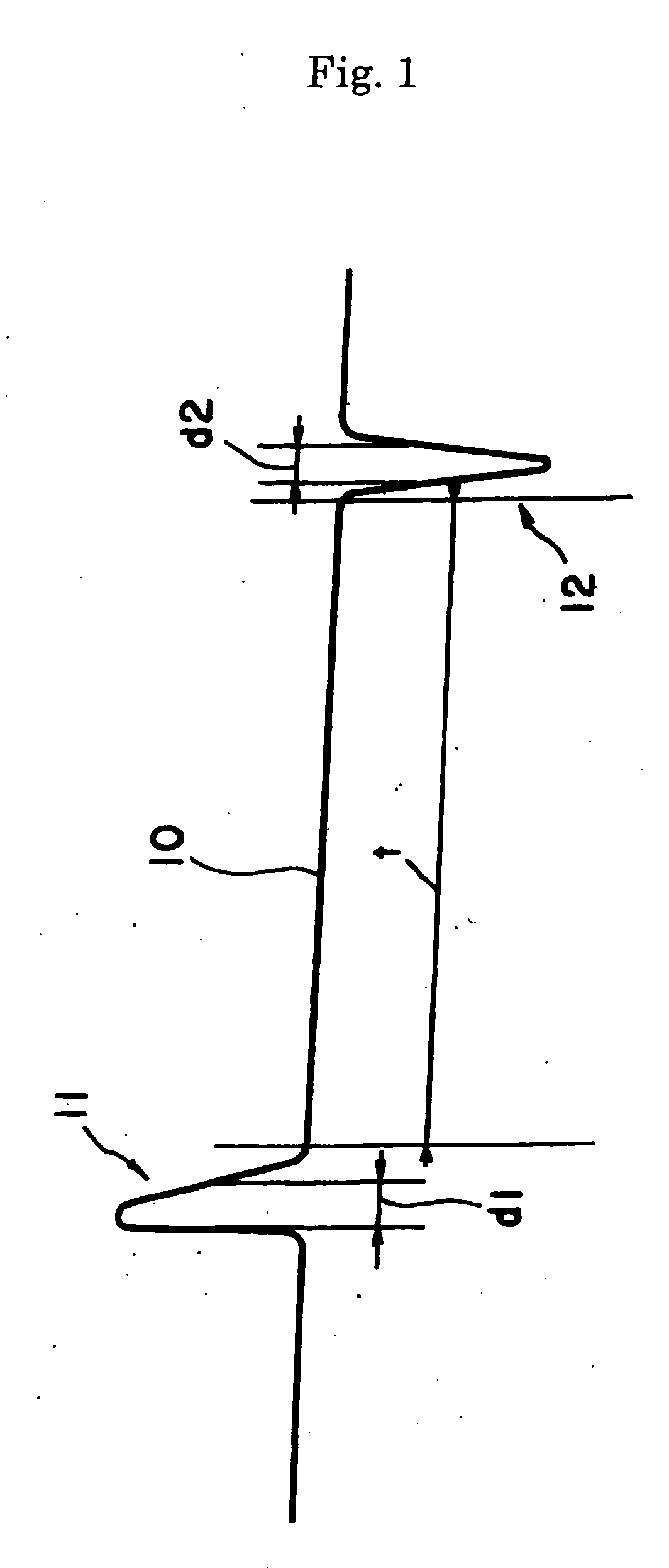
[0076] Positive pulses 11 and negative pulses 12 were periodically and alternately applied. The positive pulse 11 had a peak value of +10.0 kV and the negative pulse 12 had a peak value of −10.0 kV. The positive pulse had a frequency of 1 to 5 kHz and the distance “t” bet...


PUM

PropertyMeasurementUnit
electron densityaaaaaaaaaa
pressureaaaaaaaaaa
off-timeaaaaaaaaaa

Abstract

A pulse voltage is applied on a process gas to generate discharge plasma. The pulse voltage has a duty ratio controlled in a range of 0.001 percent or more and 8.0 percent or less. Preferably, the discharge plasma has an electron density of 1×1010 cm−3 or larger and an electron temperature of 1.5 eV or lower at a supplied power of 1.0 W/cm2 or more per a unit area of a discharge electrode.

Description

BACKGROUND OF THE INVENTION [0001] 1. Field of the Invention [0002] The present invention provides a method of generating discharge plasma. [0003] 2. Related Art Statement [0004] According to Japanese patent publication No. 2004-270022A, a nano-pulse electric power source having a pulse width of 1000 nsec or smaller is used to form a diamond-like carbon film under atmospheric pressure. [0005] Japanese patent publication No. H09-312280A disclosed that pulse discharge is maintained at an off-time of pulse discharge of 0.5 μs to 30 μs. The duty ratio of the pulse voltage is as large as 10 percent or higher and so-called microwave (high frequency wave of 2.45 GHz) is converted to pulse wave. [0006] According to Japanese patent No. 3705977B, the modulation period is made 10 to 500 μs and the duty ratio is made 10 to 80 percent. Also according to this method, as a source for generating plasma, high frequency wave of 0.4 to 13.56 MHz is converted to pulse wave for use in etching process. [...

Claims


Application Information

Patent Timeline
Patent Type & Authority Applications(United States)
IPC IPC(8): H01L21/306
CPCH01J37/32146H01J37/32091
Inventor SAITO, TAKAOTERAZAWA, TATSUYAKONDO, YOSHIMASA
Owner NGK INSULATORS LTD
Why Eureka
Try Eureka