High performance mass storage systems

a mass storage and high-performance technology, applied in the field can solve the problems of slower than the integrated circuit (ic) memory device, the operation of the hierarchical memory system is actually very complex, and the dram device used for main memory is not fast enough to provide data at such a high transfer rate, so as to improve the performance of hd and cd data storage systems, improve the performance of data storage systems, and reduce the cost of data storage systems

Inactive Publication Date: 2007-08-02
SHAU JENG JYE
View PDF1 Cites 15 Cited by
  • Summary
  • Abstract
  • Description
  • Claims
  • Application Information

AI Technical Summary

Benefits of technology

[0010] The primary objective of this invention is, therefore, to provide practical methods to improve performance of data storage systems. The other objective is to reduce the cost of data storage systems. Another objective is to provide solutions for the memory overload problem. It is also a major objective of the present invention to provide efficient methods to improve the performance of HD and CD data storage systems. These and other objectives are accomplished by novel methods in the data storage control mechanisms.

Problems solved by technology

However, they are slower than integrated circuit (IC) memory devices such as dynamic random access memory (DRAM) or static random access memory (SRAM).
The DRAM device used for main memory is not fast enough to provide data at such a high transfer rate.
The operation of hierarchical memory system is actually very complex.
However, it is not designed to handle the situation when a large memory block is required.
When we are going back to access the first 256K, we will get cache misses all the time.
The net result is that L2 cache is completely useless under this situation.
In this case the L2 cache actually slow down the data access procedure due to the overhead needed to lookup and to update the L2 cache.
One obvious solution for the above problem is to have a 512K L2 cache, but that doubles the cost, and that does not solve the problem when we need to access a bigger data block.
Even if we use a cache large enough to store the whole data block, the system performance is still degraded.
This solution sacrifices the performance for large data access, but it saves the cache capacity for smaller accesses.
The same problem exists in every level of the hierarchical data storage system.
At high level caches a relatively small data block is enough to cause the above problems.
If we declare any data block that can cause the problem at any level as not cacheable, the whole cache system won't be very useful.
This and other current art solutions minimized the damages of the memory overload problem for current art system, but they do not actually solve the problem.
These “solutions” also create complexity in control mechanism.
Another commonly experienced memory overload problem happens on main memory.
If a program tries to access a memory block larger than the size of the main memory, the program will spend most of time swapping data between the hard disk and the main memory, and the program will run extremely slow.
There is no elegant solution for a current data storage system to solve this main memory overload problem.
The difficulty comes from the fact that hard disk (HD) data access time is about one million times slower than typical IC devices. FIG. 1(c) is a simplified diagram describing the structure of a hard disk (HD) unit.
HD devices are always by far slower than IC storage devices, especially in access time.
The hard disk industry has been constantly improving the density and data transfer rate of HD devices, but there is little progress in improving the access time.
Due to mechanical nature of the seek mechanism, it is very difficult to improve seek time by changing the HD devices.
However, most of hard disk activities need to access large amount of data.
Using a small DRAM cache will have little advantage, while using a big DRAM cache will increase cost dramatically.
Current art DRAM cache for HD is therefore found to be ineffective.
This solution is very expensive.
That often becomes the bottleneck for current art data storage systems.

Method used


Image

  • High performance mass storage systems
  • High performance mass storage systems
  • High performance mass storage systems

Examples


Embodiment Construction

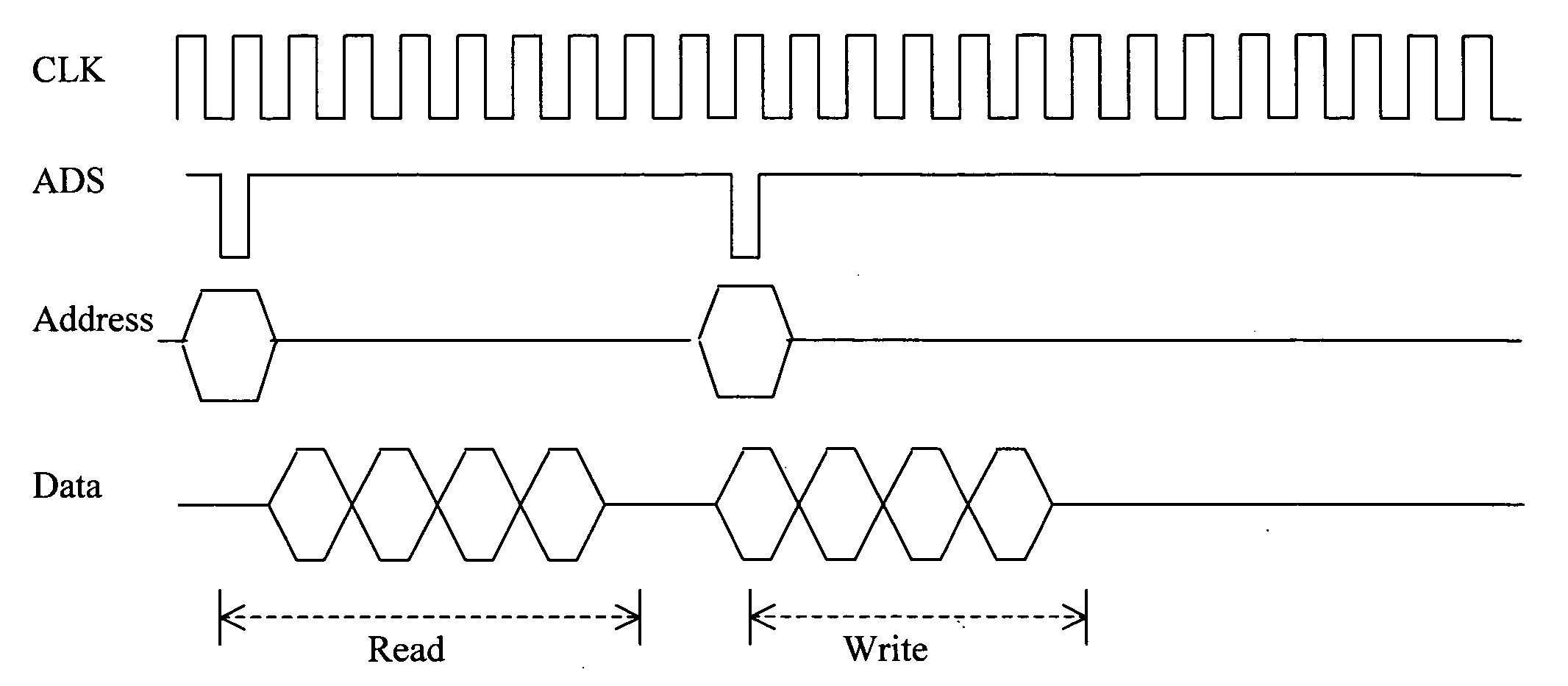
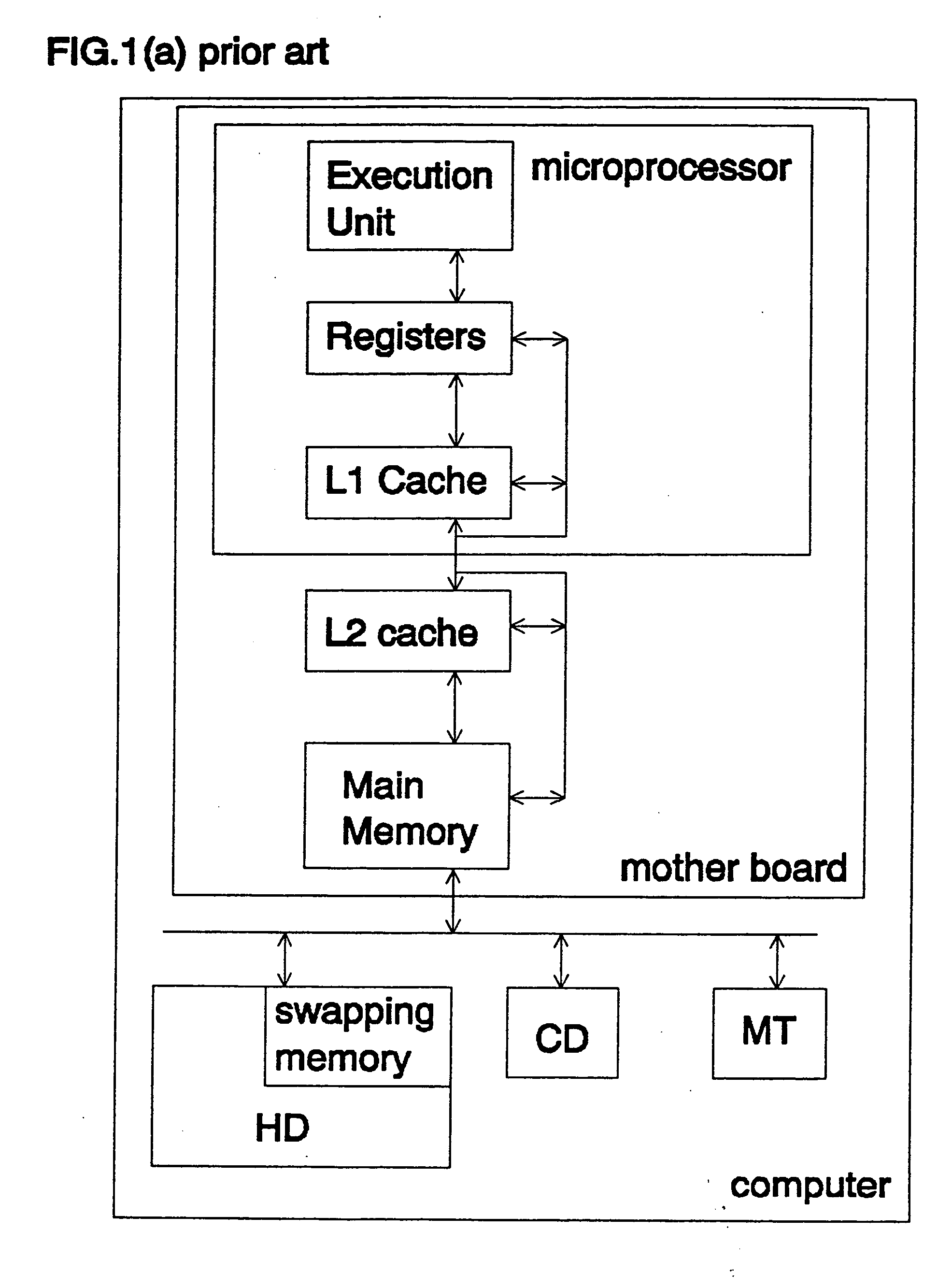
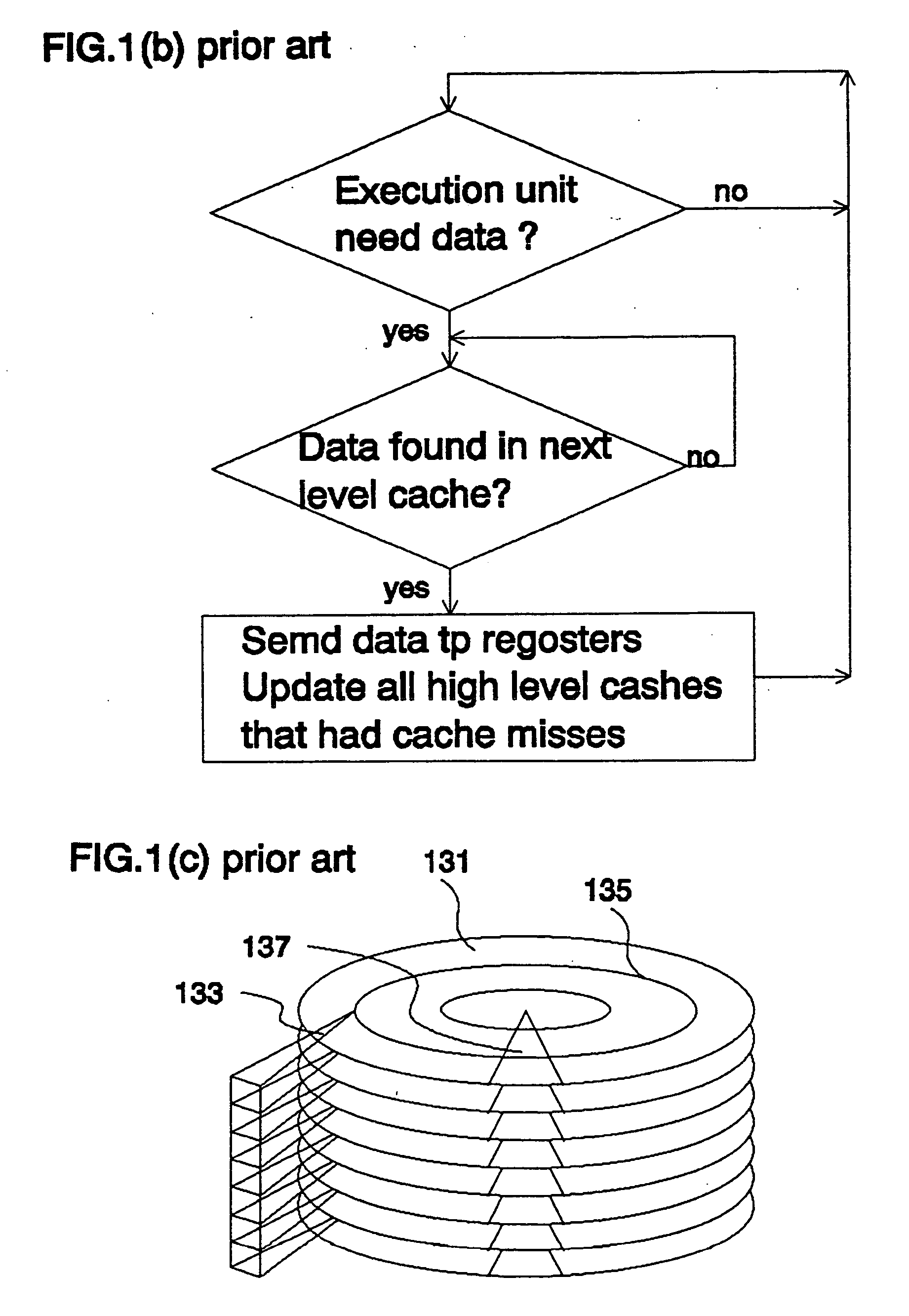
[0033] Prior art data storage systems assume that DRAM is slower than SRAM, and hard disk is slower than DRAM. Based on these assumptions, a small SRAM is used as the cache for larger DRAM, and a smaller DRAM is used to store recently used data for a larger hard disk. Relying on the principle of locality, such hierarchical data storage system can achieve reasonable performance at reasonable cost. On the other hand, current art system is highly inefficient in accessing large data blocks due to the memory overload problem discussed in background sections. In addition, current art cache memories are not optimized for burst mode memory devices. The relationship between L2 cache and main memory is used as an example to illustrate the inefficiency of current art cache.

[0034] FIGS. 2(a,b) compare the memory operation between SRAM and DRAM. For an SRAM memory read operation, typically the first data set (201) will be ready 2 clocks after the address strobe (ADS) indicating address is ready...


PUM


Abstract

A data access system for accessing data stored in a first and a second memory devices. The first and second memory devices have a difference of latency ΔL that constitutes a time-duration by which the first memory device starts an initial data access earlier than in the second memory device. A data access controller is implemented to simultaneously access data in the first and second memory devices and to stop accessing data in the first memory device once a data access operation has begun in the second memory device. Therefore, the first memory device stored data only accessed initially in a time duration corresponding substantially to the difference of latency ΔL before the data access operations is started in the second memory device.

Description

[0001] This Application claims a Priority Filing Date of Aug. 20, 2002 benefited from a previously filed Application 60 / 404,736 filed by the same inventor of this Application.FIELD OF THE INVENTION [0002] The present invention relates to data storage systems, and more particularly to methods for improving the system performance of mass data storage systems. BACKGROUND OF THE INVENTION [0003]FIG. 1(a) is the system block diagram for a typical computer data storage system. When the computer is not active, raw data are stored in nonvolatile storage devices such as hard disks (HD), compact disks (CD), or magnetic tapes (MT). These mass storage units (MSU) can store large amount of data at low cost. However, they are slower than integrated circuit (IC) memory devices such as dynamic random access memory (DRAM) or static random access memory (SRAM). The computer does not process the raw data in MSU directly. Software programs with properly formatted instruction and data structure must be ...

Claims


Application Information

Patent Timeline
Patent Type & Authority Applications(United States)
IPC IPC(8): G11C15/02
CPCG06F13/4243
Inventor SHAU, JENG-JYE
Owner SHAU JENG JYE
Why Eureka
Try Eureka