
Optical film, method for producing same, and polymer liquid crystal particle

a technology of optical film and liquid crystal particles, applied in the field of optical film, can solve the problems of unnecessary scattering of image information output from inside the display, the scattering of external light on the surface, and the scattering of image information output from the display to enlarge the viewing angle, so as to reduce the scattering of light, suppress the mixing of colors, and increase the direct transmittance of light entering at 30°

Inactive Publication Date: 2007-08-09
TOMOEGAWA PAPER CO LTD
View PDF4 Cites 3 Cited by
  • Summary
  • Abstract
  • Description
  • Claims
  • Application Information

AI Technical Summary

Benefits of technology

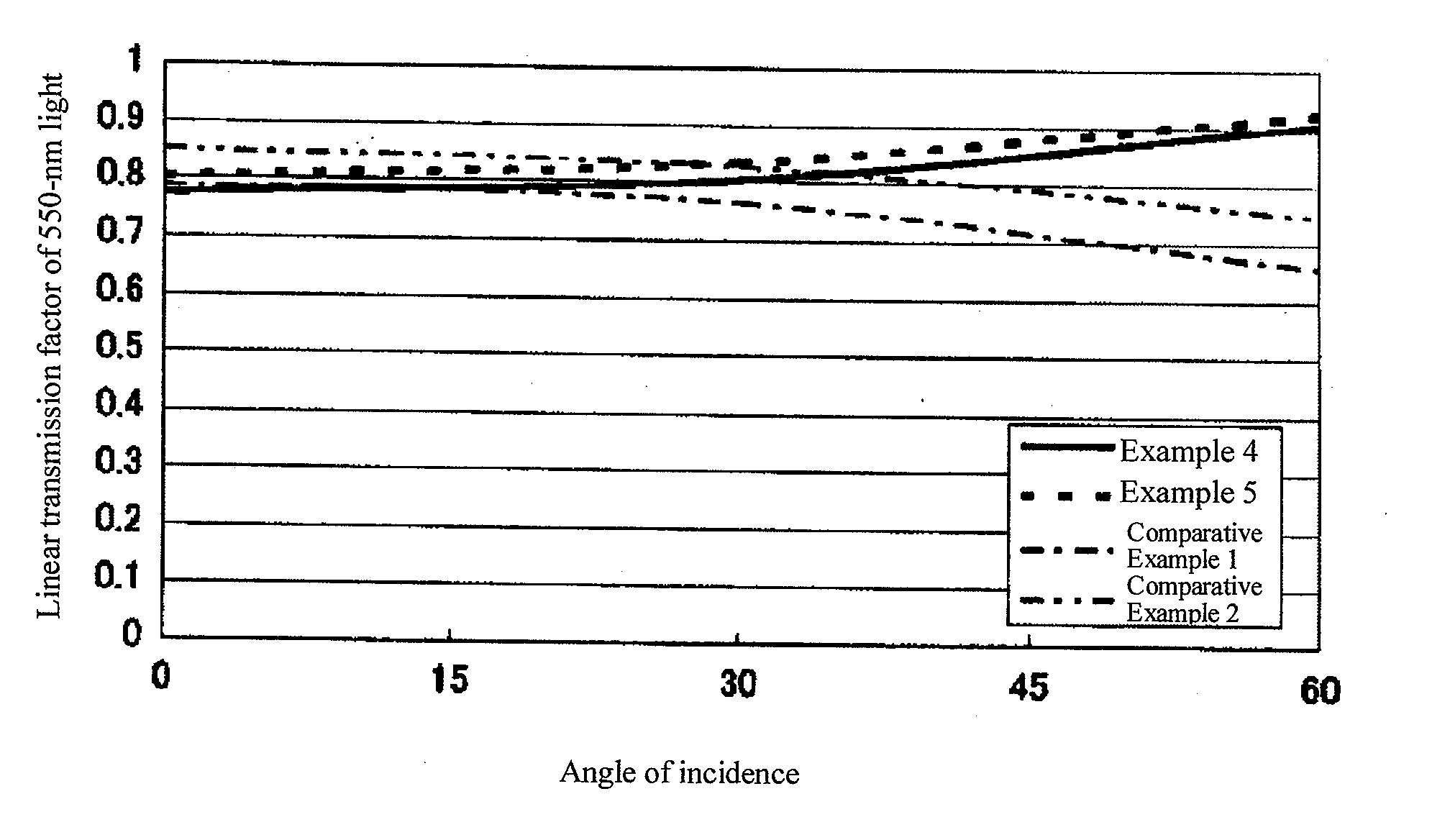
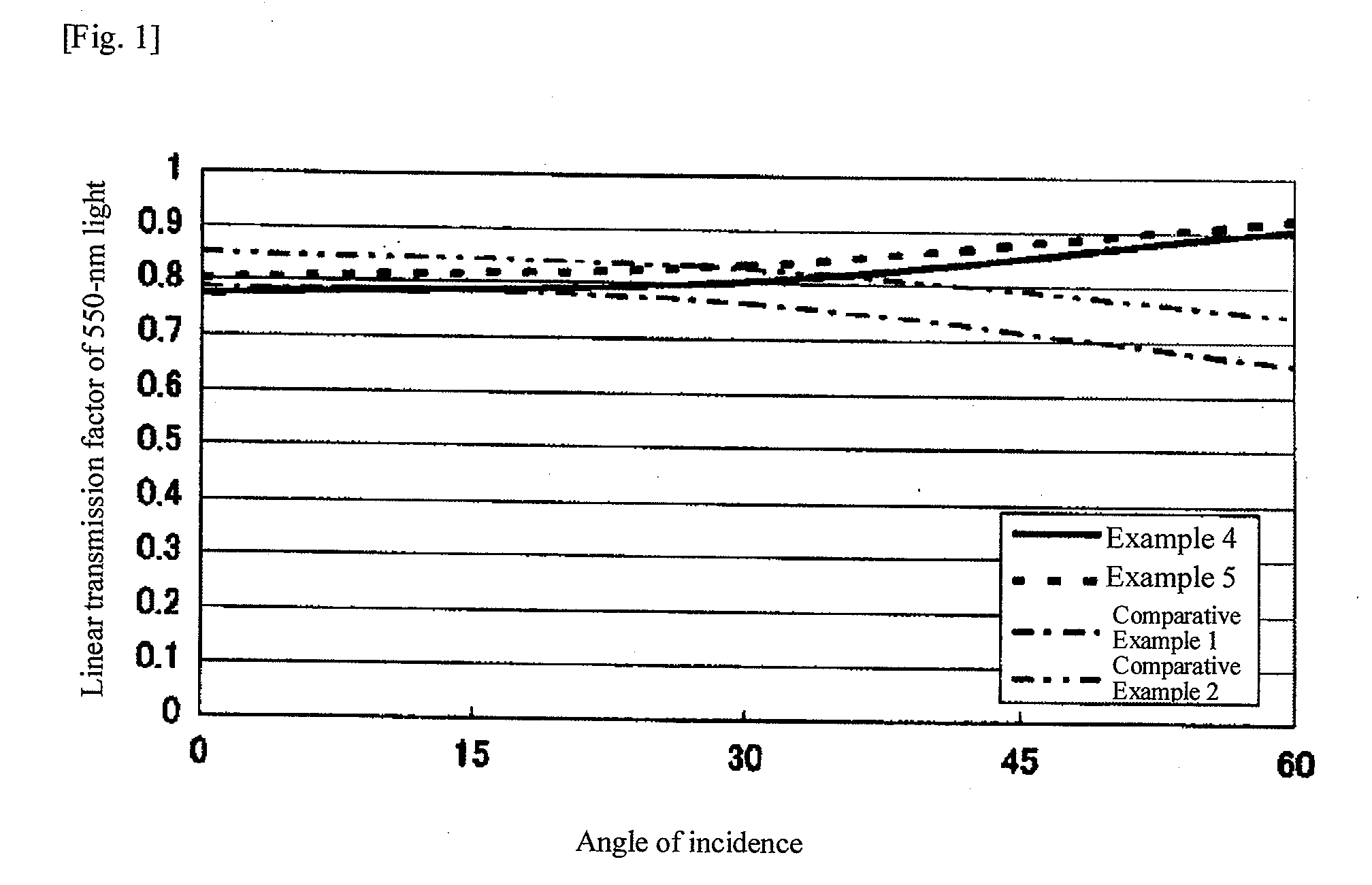
[0021] Generally with a film having a layer where fine particles are dispersed in a transparent resin phase, the direct transmittance of light with a wavelength of 550 nm entering the film is higher at an angle of incidence of 0° than at an angle of incidence of 30°. This is because light entering the film at an angle has a longer optical path in the film. As a result, more light passes the interface formed by the polymer layer and transparent fine particles, each having a different refractive index, and consequently light is caused to scatter more intensely.
[0022] On the other hand, the optical film proposed by the present invention has one of the transparent resin phase or transparent fine particle formed by an optical anisotropic polymer, while the other formed by an optical isotropic resin, to add characteristics opposite to those of general films. To be more specific, under the present invention one of the transparent resin phase or transparent fine particle is constituted by an optical anisotropic polymer, and refractive index nx or ny in the in-plane direction of the transparent resin phase and refractive index nz, in the normal direction are adjusted with respect to the refractive index of the transparent fine particle. This way, the differential refractive index between the transparent resin phase and transparent fine particle when light enters the film at 30° becomes smaller than the differential refractive index when light enters at 0°, and thus scattering of light entering at 30° becomes weaker than scattering of light entering at 0°. As a result, the direct transmittance of light entering at 30° becomes higher. In other words, the optical film proposed by the present invention can suppress mixing of colors by reducing the scattering of light entering at angles, because the differential refractive index of the transparent resin phase and transparent fine particle is greater when light enters straight ahead, while the differential refractive index becomes smaller when light enters at angles. This provides the effect of suppressing blurry image and reduced contrast. Accordingly, the optical film proposed by the present invention can be used suitably for the purpose of adding antiglare property to liquid crystal displays (LCDs), plasma display panels (PDPs), CRTs, ELs and other image display devices.

Problems solved by technology

Of the aforementioned technologies, the last one, or the antiglare treatment using a resin binder and clear fine organic particles, can cause external light to scatter on the surface due partly to the irregularities formed by the fine particles and partly to the differential refractive index between the resin binder and fine particle.
In addition, if this technology is used on liquid crystal displays whose viewing angle is limited due to the display mechanism, image information output from the display can be scattered to enlarge the viewing angle.
Although unwanted reflection on the display surface can be prevented, however, displays that have been given the aforementioned antiglare treatment also cause unnecessary scattering of image information output from inside the display.
This gives rise to problems such as blurry image and reduced contrast.
However, the above method presented difficulty in terms of forming surface irregularities and therefore was short of providing sufficient antiglare performance against unwanted reflection of external light.

Method used


Image

  • Optical film, method for producing same, and polymer liquid crystal particle
  • Optical film, method for producing same, and polymer liquid crystal particle
  • Optical film, method for producing same, and polymer liquid crystal particle

Examples


example 1

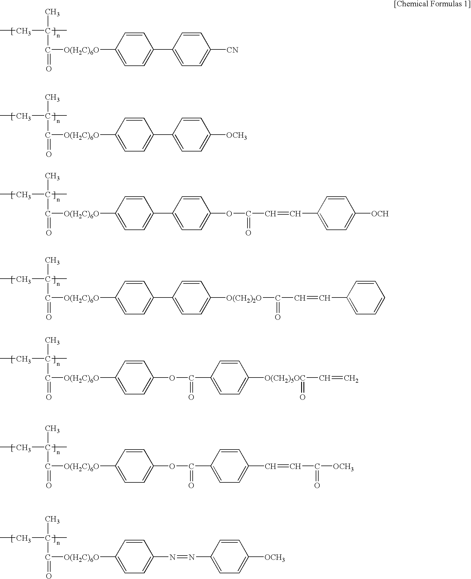
[0044] As a polymeric monomer, 3.0 g of the compound expressed by formula (1) below, 2.0 g of the compound expressed by formula (2) below, and 0.02 part of 2,2′-azobis(isobutyl nitrile) used as a polymerization initiator, were mixed in 200 ml of 0.10% aqueous polyvinyl alcohol solution at 5° C. to obtain a reaction solution of polymeric monomer.

[0045] This reaction solution of polymeric monomer was agitated using a homogenizing mixer operated at 5,000 rpm to prepare an emulsion of polymeric monomer. This emulsion was further agitated using a homogenizing mixer operated at 5,000 rpm in the presence of nitrogen to cause polymerization under heat at 80° C. for 5 hours. The resulting solution was filtered to obtain 4.3 parts of polymer liquid crystal fine particles. When the obtained polymer liquid crystal fine particles were observed using a scanning electron microscope, the particles had a spherical shape. The particle size measured by the Coulter counter method was 5.1 μm, and the a...

example 2

[0046] As a polymeric monomer, 3.0 g of the compound expressed by formula (1) above, 2.0 g of the compound expressed by formula (2) above, and 0.02 g of 2,2′-azobis(isobutyl nitrite) used as a polymerization initiator, were mixed in 200 ml of THF at 5° C. to obtain a reaction solution of polymeric monomer. This reaction solution of polymeric monomer was agitated with a magnetic stirrer in the presence of nitrogen to cause polymerization under heat at 54° C. for 24 hours, and then cooled and filtered to obtain 4.1 g of white high-molecular liquid crystal compound. When measured by GPC, the average volumetric molecular weight of this high-molecular liquid crystal compound was approx. 80000.

[0047] Next, 2.0 g of the high-molecular liquid crystal compound was blended with 20 g of anisole and dissolved under heat at 80° C. to obtain a solution. The resulting solution was cooled to 5° C., and then filtered to obtain 1.9 g of polymer liquid crystal fine particles. When observed on a scann...

example 3

[0048] 2.0 g of the high-molecular liquid crystal compound obtained in Example 2 was dissolved in 40 g of chloroform to obtain a solution. Next, the solution was atomized by a spray dryer into droplet with a particle size of 10 μm, and then dried under hot air of 100° C. to obtain 0.6 g of polymer liquid crystal fine particles. When observed on a scanning electron microscope, the obtained polymer liquid crystal fine particles had a spherical shape, and their particle size was measured as approx. 4.0 μm by the Coulter counter method.


PUM

PropertyMeasurementUnit
particle sizeaaaaaaaaaa
Raaaaaaaaaaa
wavelengthaaaaaaaaaa

Abstract

The present invention provides an optical film that can be suitably used for antiglare treatment to suppress blurry image and reduced contrast, as well as a method of producing such optical film. The optical film proposed by the present invention has a transparent base and a coating layer which is provided on at least one side of the transparent base and where transparent fine particles of 0.5 to 10 μm in average particle size are dispersed in a transparent resin phase, and one of the transparent resin phase or transparent fine particle contains a molecule-oriented high-molecular liquid crystal compound while the other is made of an optical isotropic resin.

Description

TECHNICAL FIELD [0001] The present invention relates to an optical film exhibiting anisotropic scattering property that can be suitably used for liquid crystal displays (LCDs), plasma display panels (PDPs), CRTs, ELs and other image display devices, as well as a method of producing such optical film, and also relates to polymer liquid crystal fine particles made of a high-molecular material containing liquid crystal mesogens, to be used in the aforementioned optical film. BACKGROUND ART [0002] Image display devices such as the aforementioned LCDs, PDPs, CRTs and ELs (hereinafter referred to as “displays”) are used in a wide range of fields including TV and computer and are undergoing remarkable innovation. In particular, LCDs have become immensely popular as slim, lightweight and versatile displays for use in personal computers, mobile phones, TVs, digital cameras, PDAs and various other devices. [0003] When these displays are used in relatively bright areas such as outdoors and und...

Claims


Application Information

Patent Timeline
Patent Type & Authority Applications(United States)
IPC IPC(8): G02B27/00G02B5/02B32B7/02G02B1/10G02B1/11G02B1/12G02B5/30G02F1/1335
CPCC09K19/3852C09K19/544G02B1/111G02F2201/38G02B5/3016G02F1/133504G02B1/12G02B5/02G02B1/10G02F1/1335
Inventor MURATAHIGASHI, KENSAKUKAWATSUKI, NOBUHIRO
Owner TOMOEGAWA PAPER CO LTD
Learn More