
Spatially patterned substrates for chemical and biological sensing

a substrate and spatial pattern technology, applied in the field of spatial pattern substrates, can solve the problems of inability to detect absorption or spectral scattering features from surface interactions, the primary challenge of sensor design, and the inability to achieve isolation from strong background signals, so as to enhance spectroscopic signal isolation and detection, and improve sensing

Inactive Publication Date: 2007-08-16
ASB INT SERVICES LTD
View PDF6 Cites 23 Cited by
  • Summary
  • Abstract
  • Description
  • Claims
  • Application Information

AI Technical Summary

Benefits of technology

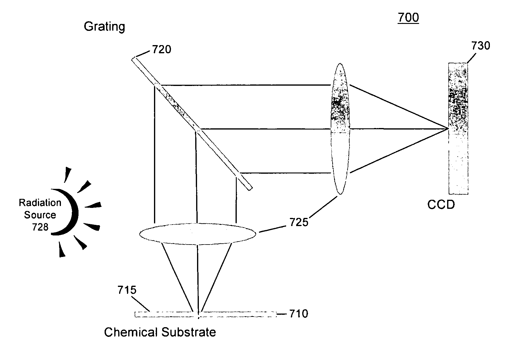
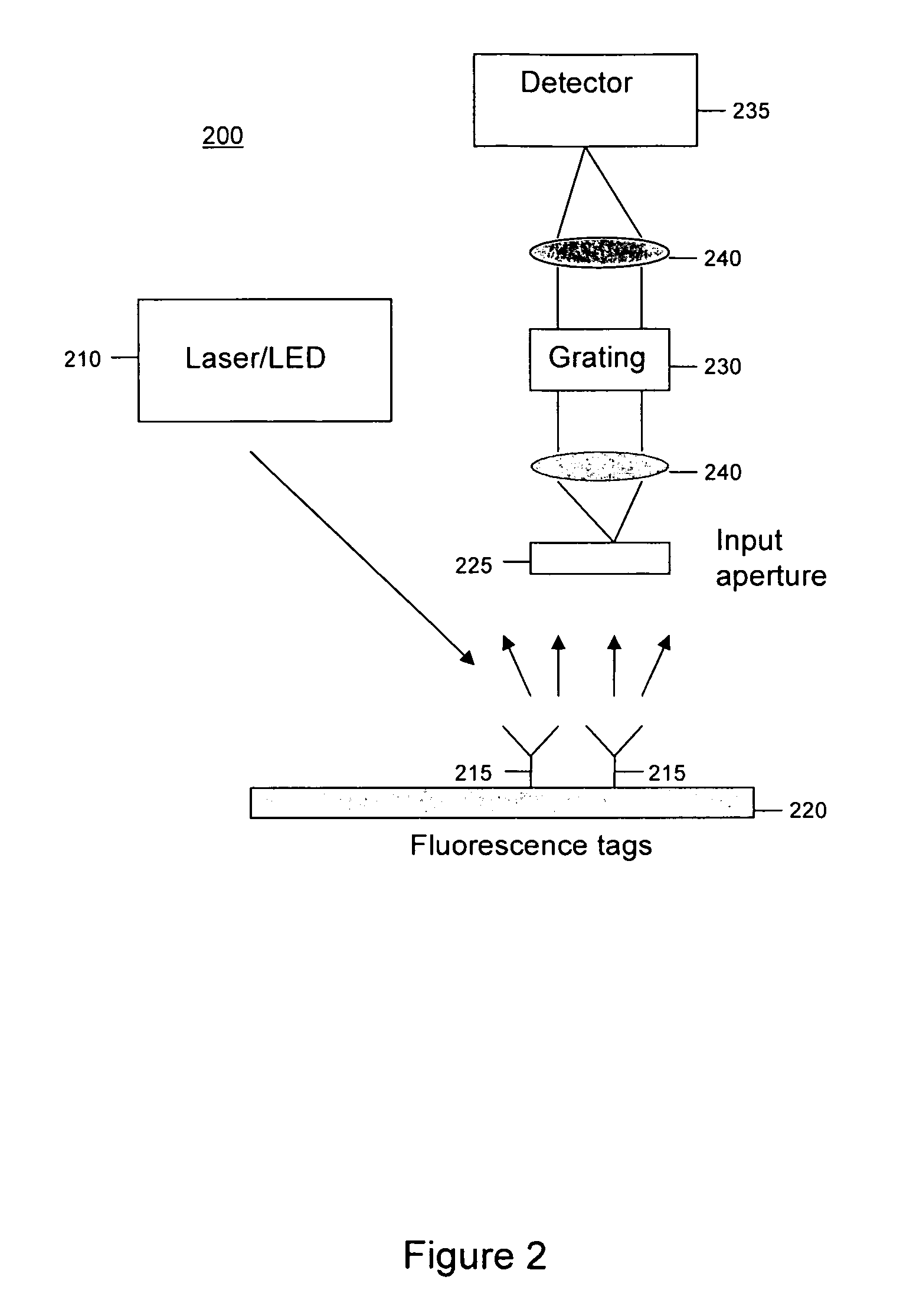
[0007] Embodiments of the present invention overcome at least some of these and other drawbacks of existing systems. Embodiments of the present invention improve sensing based on molecularly induced optical signals. For example, embodiments of the present invention enhance spectroscopic signal isolation and detection using spatial patterning of reactive areas of a testing surface. With respect to absorption, spatial patterning creates optical diffraction orders with intensity that is proportional to relevant spectral features. In the case of Raman scattering and other spectrally correlated scattering and fluorescence effects, spatial patterning enables collection of highly resolved spectral signals. In both cases, spatial patterning enables signal collection from assays that have 100 micron to 1 cm cross sections. This cross section is larger than typical sample cross sections used with conventional imaging spectrometers. Spatial patterning also enables parallel data collection from multiple assay components.

Problems solved by technology

Given a molecular recognition system, however, digital transduction is the primary challenge of sensor design.
For a number of reasons, detection of absorption or spectral scattering features from surface interactions is difficult with conventional spectrometers.
Further, isolation from strong background signals is not achieved.
In addition, conventional spectroscopic sensors are not well adapted to integration of spectral signals from large area samples.
For example, when working with highly scattering diffuse samples or when using low light techniques such as fluorescence and Raman scattering, conventional grating-based spectrometers that use slits produce less than desirable measurement sensitivity, specificity, and selectivity.
Further, conventional slit-based spectrometers are not well suited for the large chemical interaction areas that are used in chemical and biological sensing.
However, large surface areas are difficult to cover using conventional slit-based spectrometers.

Method used


Image

  • Spatially patterned substrates for chemical and biological sensing
  • Spatially patterned substrates for chemical and biological sensing
  • Spatially patterned substrates for chemical and biological sensing

Examples


Embodiment Construction

[0023] While specific embodiments of the invention are discussed herein and are illustrated in the drawings appended hereto, the invention encompasses a broader scope than the specific subject matter described and illustrated. As would be appreciated by those skilled in the art, the embodiments described herein provide but a few examples of the broad scope of the invention. There is no intention to limit the scope of the invention only to the embodiments described.

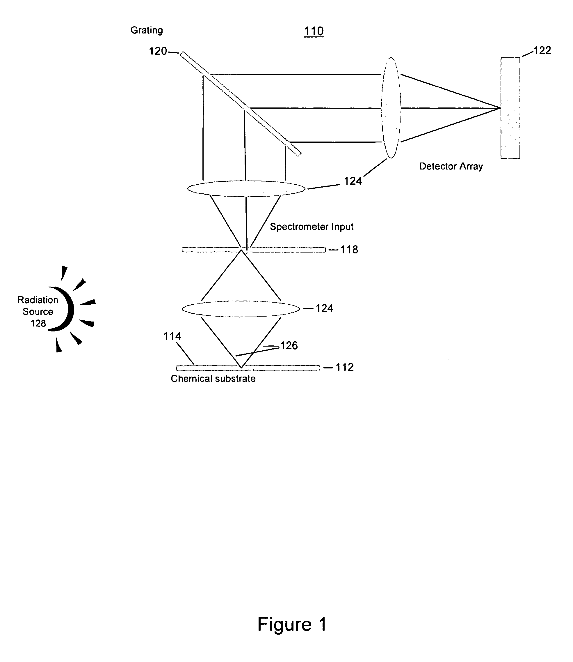
[0024]FIG. 1 illustrates a conventional dispersive spectrometer 110. Spectrometer 110 may include a substrate 112 that provides a testing surface 114, a source 128, a mask 118 that includes one or more transmissive and opaque elements, a diffractive element 120, a detector array 122, one or more optical elements 124 that guide radiation generated by a source 128 within spectrometer 110, and / or other components. The term “radiation” used herein includes all types of electromagnetic radiation, such as ultraviolet (UV) radia...


PUM


Abstract

A system and method are provided for imaging a test substrate having a test surface that is configured to enable spectroscopic detection of one or more chemical or biological species, wherein the test surface includes a testing site disposed thereon according to a predetermined spatial pattern. The test substrate is provided in an image plane or a Fourier Transform plane of a sensor. The invention provides high throughput and high spectral resolution.

Description

FIELD OF THE INVENTION [0001] This invention is directed to a system and method of using spatially patterned substrates to isolate and accentuate optical signals from chemical sensors. More particularly, embodiments of the present invention use Fourier and focal plane aperture coding to produce molecule-specific scattering and image features in optically transduced chemical and biological sensors. BACKGROUND OF THE INVENTION [0002] Molecular detection based on the interaction of a receptor molecule and a target molecule is the basis of chemical and biological sensing. Given a molecular recognition system, however, digital transduction is the primary challenge of sensor design. Molecular interactions may change electronic, optical or acoustic properties of a sample. [0003] Molecular interactions may modulate the scattering, fluorescence, absorption or other properties of a sample under test. Typically theses properties are monitored by placing a sample carrier in a conventional spect...

Claims


Application Information

Patent Timeline
IPC IPC(8): G01J3/44G01N21/64G01N21/65
CPCG01N21/31G01N21/554G01N21/6452G01N21/648G01N2201/062G01N2021/317G01N2021/6417G01N2201/06113G01N21/658
Inventor BRADY, DAVID J.SULLIVAN, MICHAEL E.POTULURI, PRASANT
Owner ASB INT SERVICES LTD
Learn More